QLA23xx Board Components | 2 – Hardware Installation |
SERIAL NUMBER
J1
1 ![]()
![]()
![]()
![]()
![]()
![]()
![]()
![]()
![]() 3
3
J2
J3
J4
1 ![]()
![]()
![]()
![]()
![]() 3
3
ISP CHIP |
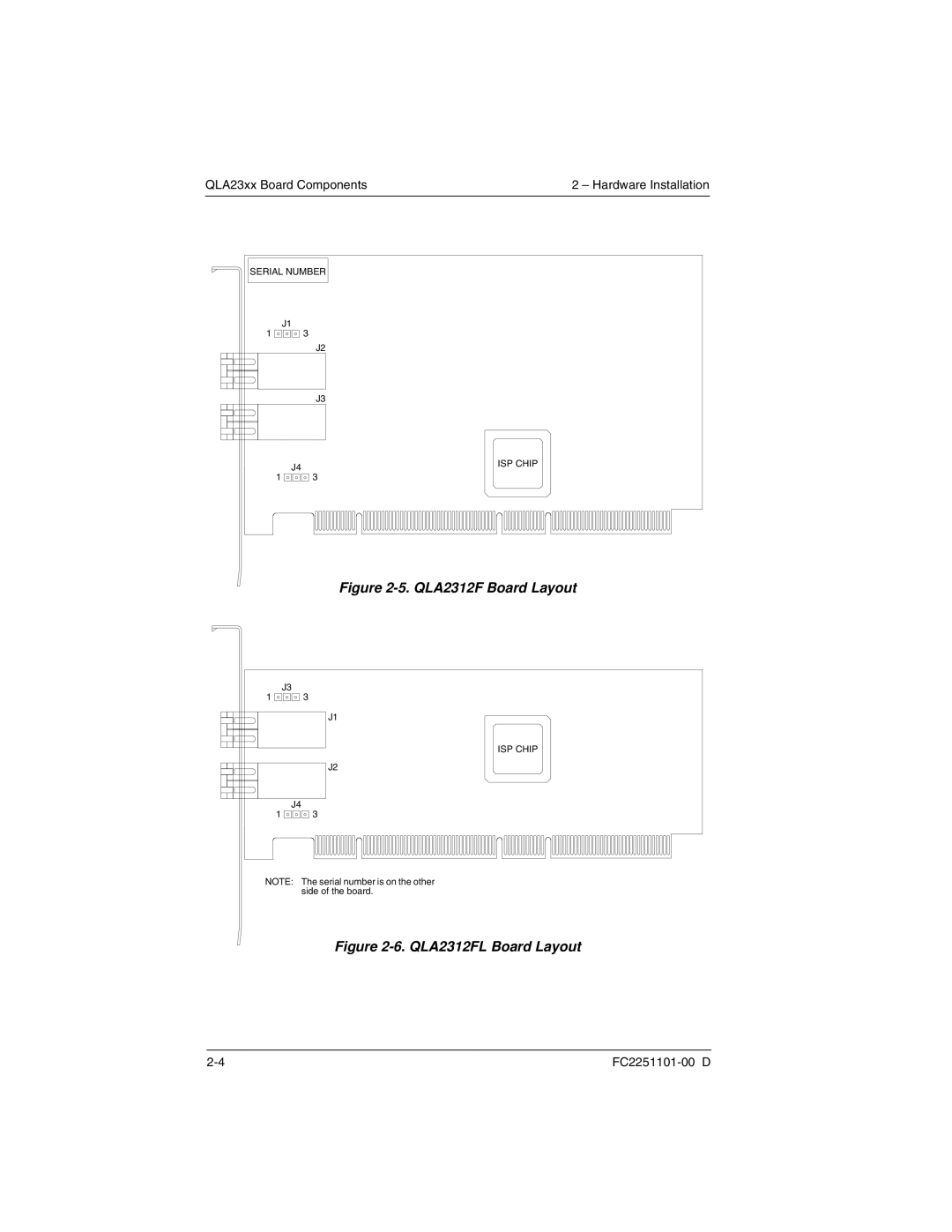
Figure 2-5. QLA2312F Board Layout
J3
1 ![]()
![]()
![]()
![]()
![]() 3
3
J1
J2
J4
1 ![]()
![]()
![]()
![]()
![]() 3
3
ISP CHIP |
NOTE: The serial number is on the other side of the board.
