QLA23xx Board Components | 2 – Hardware Installation |
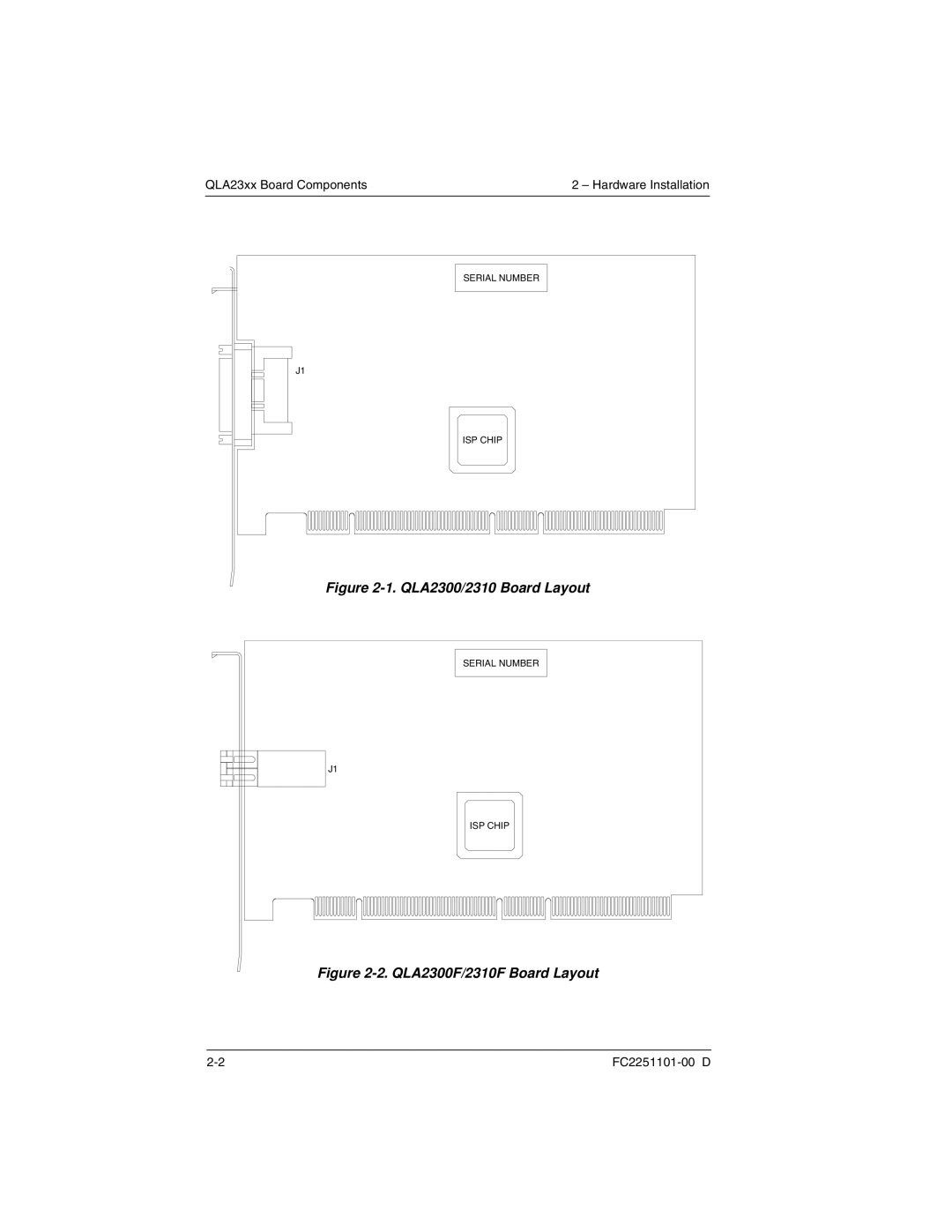
SERIAL NUMBER
J1
ISP CHIP |
Figure 2-1. QLA2300/2310 Board Layout
SERIAL NUMBER
J1
ISP CHIP
QLA23xx Board Components | 2 – Hardware Installation |
SERIAL NUMBER
J1
ISP CHIP |
SERIAL NUMBER
J1
ISP CHIP