Speakon™ Outputs
CMX amplifiers offer a choice of output connections, with two NL4MD Speakon™ jacks and a terminal block connector. (Figure 28 through Figure 30)
The Speakon™ connector is designed specially for high‑power speaker connections. It locks in place, prevents shock hazard, and assures the correct polarity.
Each channel accepts a normal
For easier insertion, use the newer‑style NL4FC Speakon™ connectors with quick‑lock thumb latches.
Speaker Cabling
Larger wire sizes and shorter lengths minimize both loss of power and degradation of damping factor. Do not place speaker cables next to input wiring.
WARNING: To prevent electric shock, do not operate the amplifier with any of the conductor of the speaker wire exposed.
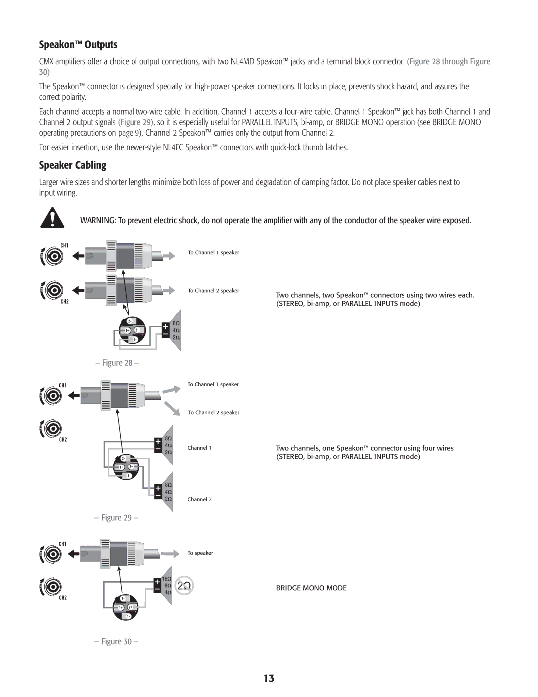
To Channel 1 speaker |
|
To Channel 2 speaker | Two channels, two Speakon™ connectors using two wires each. |
| |
| (STEREO, bi‑amp, or PARALLEL INPUTS mode) |
— Figure 28 —
To Channel 1 speaker
To Channel 2 speaker
Channel 1
Channel 2
— Figure 29 —
To speaker
— Figure 30 —
Two channels, one Speakon™ connector using four wires (STEREO, bi‑amp, or PARALLEL INPUTS mode)
BRIDGE MONO MODE
13