Connections
Inputs
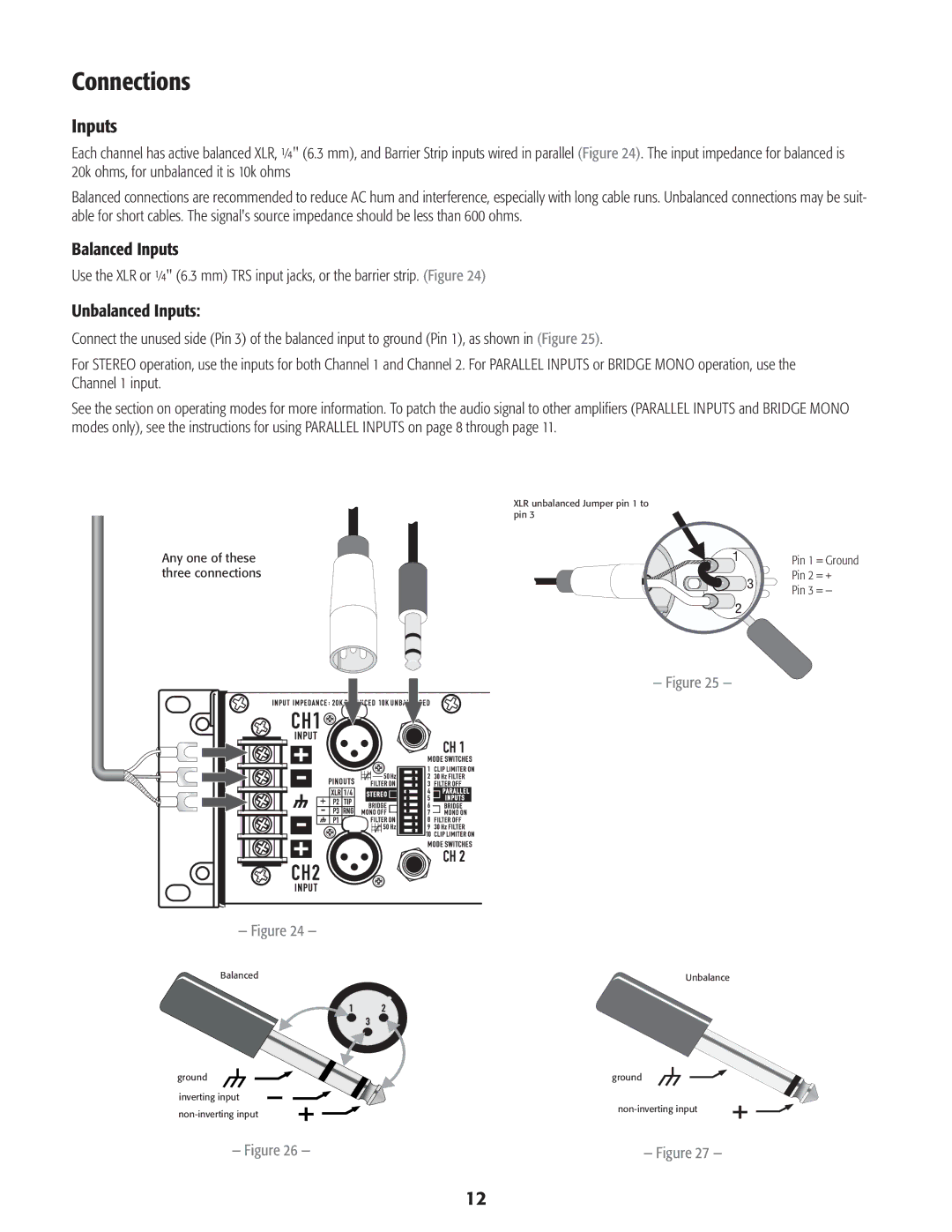
Each channel has active balanced XLR, ¼" (6.3 mm), and Barrier Strip inputs wired in parallel (Figure 24). The input impedance for balanced is 20k ohms, for unbalanced it is 10k ohms
Balanced connections are recommended to reduce AC hum and interference, especially with long cable runs. Unbalanced connections may be suit- able for short cables. The signal's source impedance should be less than 600 ohms.
Balanced Inputs
Use the XLR or ¼" (6.3 mm) TRS input jacks, or the barrier strip. (Figure 24)
Unbalanced Inputs:
Connect the unused side (Pin 3) of the balanced input to ground (Pin 1), as shown in (Figure 25).
For STEREO operation, use the inputs for both Channel 1 and Channel 2. For PARALLEL INPUTS or BRIDGE MONO operation, use the Channel 1 input.
See the section on operating modes for more information. To patch the audio signal to other amplifiers (PARALLEL INPUTS and BRIDGE MONO modes only), see the instructions for using PARALLEL INPUTS on page 8 through page 11.
XLR unbalanced Jumper pin 1 to pin 3
Any one of these three connections
— Figure 25 —
— Figure 24 — |
Pin 1 = Ground
Pin 2 = +
Pin 3 = —
Balanced | Unbalance |
ground
inverting input non‑inverting input
ground
non‑inverting input
— Figure 26 — | — Figure 27 — |
12
