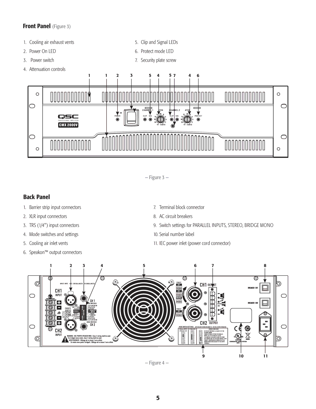
Front Panel (Figure 3)
1. | Cooling air exhaust vents | 5. | Clip and Signal LEDs |
2. | Power On LED | 6. | Protect mode LED |
3. | Power switch | 7. | Security plate screw |
4. | Attenuation controls |
|
|
1 | 1 | 2 | 3 | 5 | 4 | 5 7 | 4 | 6 |
|
|
|
| — Figure 3 — |
|
|
| |
Back Panel
1. | Barrier strip input connectors | 7. | Terminal block connector |
2. | XLR input connectors | 8. | AC circuit breakers |
3. | TRS (1/4") input connectors | 9. | Switch settings for PARALLEL INPUTS, STEREO, BRIDGE MONO |
4. | Mode switches and settings | 10. Serial number label | |
5. | Cooling air inlet vents | 11. | IEC power inlet (power cord connector) |
6. | Speakon™ output connectors |
|
|
1 | 2 | 3 | 4 | 5 | 6 | 7 |
| 8 |
|
|
|
|
|
| 9 | 10 | 11 |
|
|
|
| — Figure 4 — |
|
|
|
|
5
