Operation
AC Power Switch
Before applying power, check all connections and turn the attenuation controls fully counter clockwise to maximum attenuation.
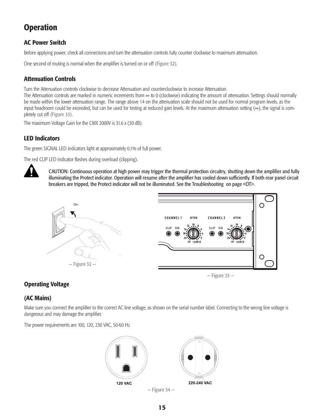
One second of muting is normal when the amplifier is turned on or off (Figure 32).
Attenuation Controls
Turn the Attenuation controls clockwise to decrease Attenuation and counterclockwise to increase Attenuation.
The Attenuation controls are marked in numeric increments from ∞ to 0 (clockwise) indicating the amount of attenuation. Settings should normally be made within the lower attenuation range. The range above 14 on the attenuation scale should not be used for normal program levels, as the input headroom could be exceeded, but can be used for testing at reduced gain levels. At the maximum attenuation setting (∞), the signal is com- pletely cut off (Figure 33).
The maximum Voltage Gain for the CMX 2000V is 31.6 x (30 dB).
LED Indicators
The green SIGNAL LED indicators light at approximately 0.1% of full power.
The red CLIP LED indicator flashes during overload (clipping).
CAUTION: Continuous operation at high power may trigger the thermal protection circuitry, shutting down the amplifier and fully illuminating the Protect indicator. Operation will resume after the amplifier has cooled down sufficiently. If both rear panel circuit breakers are tripped, the Protect indicator will not be illuminated. See the Troubleshooting on page <OT>.
On
— Figure 32 —
— Figure 33 — |
Operating Voltage
(AC Mains)
Make sure you connect the amplifier to the correct AC line voltage, as shown on the serial number label. Connecting to the wrong line voltage is dangerous and may damage the amplifier.
The power requirements are 100, 120, 230 VAC, 50‑60 Hz
— Figure 34 —
15