The Difference Between Modes
STEREO Mode
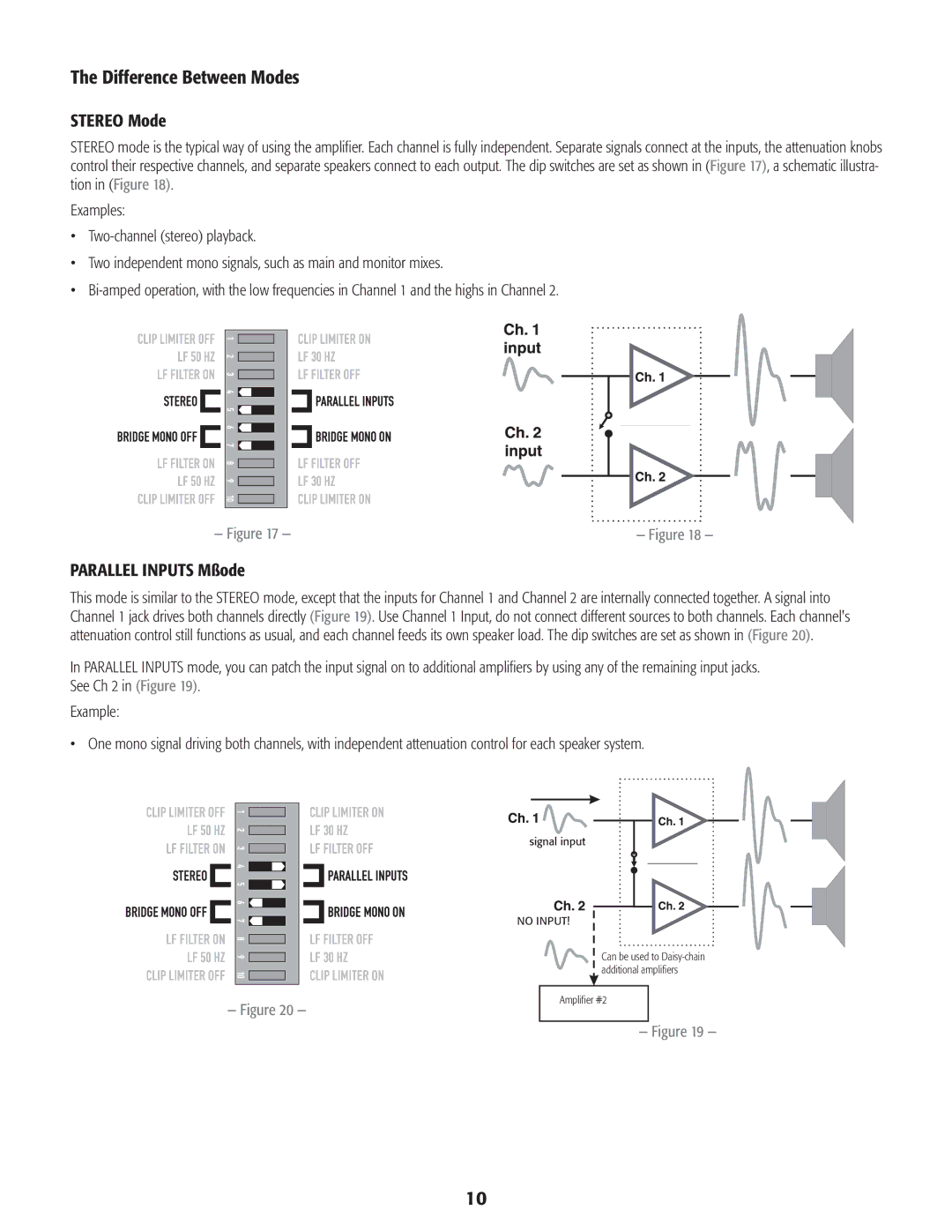
STEREO mode is the typical way of using the amplifier. Each channel is fully independent. Separate signals connect at the inputs, the attenuation knobs control their respective channels, and separate speakers connect to each output. The dip switches are set as shown in (Figure 17), a schematic illustra- tion in (Figure 18).
Examples:
•Two‑channel (stereo) playback.
•Two independent mono signals, such as main and monitor mixes.
•Bi‑amped operation, with the low frequencies in Channel 1 and the highs in Channel 2.
— Figure 17 — | — Figure 18 — |
PARALLEL INPUTS Mßode
This mode is similar to the STEREO mode, except that the inputs for Channel 1 and Channel 2 are internally connected together. A signal into Channel 1 jack drives both channels directly (Figure 19). Use Channel 1 Input, do not connect different sources to both channels. Each channel's attenuation control still functions as usual, and each channel feeds its own speaker load. The dip switches are set as shown in (Figure 20).
In PARALLEL INPUTS mode, you can patch the input signal on to additional amplifiers by using any of the remaining input jacks. See Ch 2 in (Figure 19).
Example:
•One mono signal driving both channels, with independent attenuation control for each speaker system.
signal input
NO INPUT!
Can be used to Daisy‑chain additional amplifiers
— Figure 20 —
Amplifier #2
— Figure 19 —
10
