Castile & Santa Fe CE Insert
9 Appliance Set-Up
R
A. Leveling System
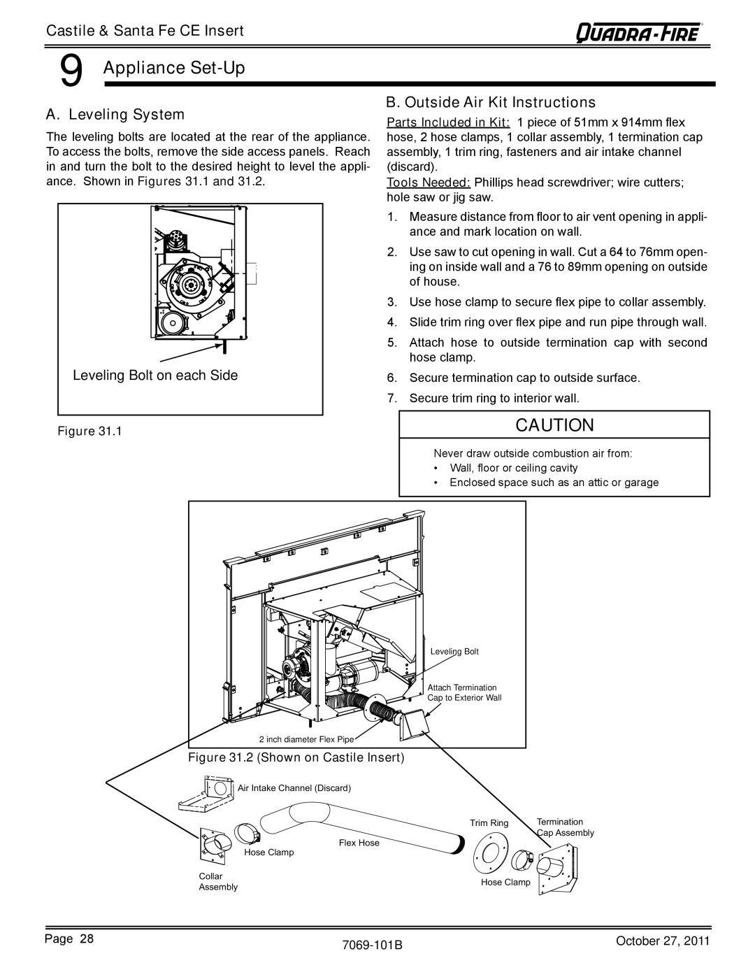
The leveling bolts are located at the rear of the appliance. To access the bolts, remove the side access panels. Reach in and turn the bolt to the desired height to level the appli- ance. Shown in Figures 31.1 and 31.2.
Leveling Bolt on each Side |
Figure 31.1
B. Outside Air Kit Instructions
Parts Included in Kit: 1 piece of 51mm x 914mm flex hose, 2 hose clamps, 1 collar assembly, 1 termination cap assembly, 1 trim ring, fasteners and air intake channel (discard).
Tools Needed: Phillips head screwdriver; wire cutters; hole saw or jig saw.
1.Measure distance from floor to air vent opening in appli- ance and mark location on wall.
2.Use saw to cut opening in wall. Cut a 64 to 76mm open- ing on inside wall and a 76 to 89mm opening on outside of house.
3.Use hose clamp to secure flex pipe to collar assembly.
4.Slide trim ring over flex pipe and run pipe through wall.
5.Attach hose to outside termination cap with second hose clamp.
6.Secure termination cap to outside surface.
7.Secure trim ring to interior wall.
CAUTION
Never draw outside combustion air from:
•Wall, floor or ceiling cavity
•Enclosed space such as an attic or garage
Leveling Bolt |
Attach Termination |
Cap to Exterior Wall |
2 inch diameter Flex Pipe |
Figure 31.2 (Shown on Castile Insert)
Air Intake Channel (Discard)
Trim Ring | Termination |
| Cap Assembly |
Flex Hose
Hose Clamp
Collar | Hose Clamp | |
Assembly | ||
|
Page 28 | October 27, 2011 | |
|
|