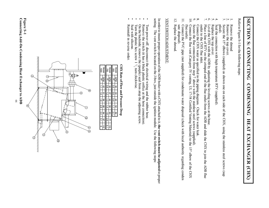
1000, 750, 500 specifications
Raypak is a renowned name in the heating industry, particularly known for its high-quality pool and spa heaters. Among their extensive product line, the Raypak 850, 500, 300, 400, and 700 models stand out for their reliability, efficiency, and cutting-edge technologies. Each model is designed to cater to different needs and applications while maintaining Raypak’s commitment to performance.The Raypak 850 is designed for larger commercial pools or residential setups requiring high output. With a powerful heat exchanger made from copper and bronze, it ensures superior heat transfer and longevity. Its digital control system provides precise temperature regulation, enhancing user experience. Moreover, it features a durable construction with weather-resistant materials, ensuring lasting performance in various environments.
The Raypak 500 model offers a balance between efficiency and compactness. It features eco-friendly technology that reduces energy consumption without sacrificing performance. The integrated thermostat allows users to maintain consistent water temperatures, making it ideal for residential pools. This model is well-regarded for its user-friendly digital display, simplifying operation and monitoring.
For those needing a more moderate capacity, the Raypak 300 is an efficient choice. It combines robust engineering with an easy-to-use interface. Its advanced ignition system improves reliability while minimizing energy waste. The Raypak 300’s compact design allows for easy installation in various spaces, making it an excellent option for smaller pools.
The Raypak 400 heats water quickly and efficiently, making it suitable for both residential pools and spas. It features a high-capacity heating system that ensures optimal performance. With a clear LED display, users can easily monitor their settings, while the integrated diagnostics provide real-time feedback for maintenance and troubleshooting.
Lastly, the Raypak 700 model is known for its versatility and robust performance. It is equipped with advanced safety features, including a high limit switch and water flow detection mechanism, to ensure safe operation. The model's energy-efficient design enhances its eco-friendliness, making it a popular choice among environmentally conscious users.
Collectively, these Raypak models exemplify superior engineering, performance, and user-friendliness. Their innovative features ensure that they meet the varied demands of pool owners while providing reliable heating solutions for leisure and relaxation. Whether for commercial or residential use, the Raypak 850, 500, 300, 400, and 700 offer unmatched quality and efficiency.

