5-5. Foot Alignment
| 4 |
| 3 |
2 | 5 |
|
1
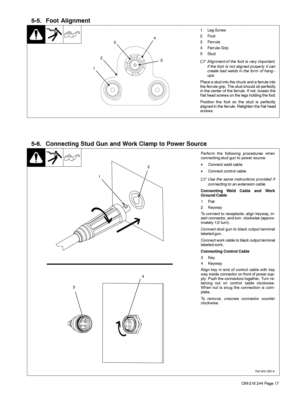
1Leg Screw
2Foot
3Ferrule
4Ferrule Grip
5Stud
.Alignment of the foot is very important,
if the foot is not aligned properly it can create bad welds in the form of hang− ups.
Place a stud into the chuck and a ferrule into the ferrule grip. The stud should sit perfectly in the center of the ferrule. If not, loosen the flat head screws on the legs holding the foot.
Position the foot so the stud is perfectly aligned in the ferrule. Retighten the flat head screws.
5-6. Connecting Stud Gun and Work Clamp to Power Source
2
1
4
3
Perform the following procedures when connecting stud gun to power source:
•Connect weld cable
•Connect control cable
.Use the same instructions provided if connecting to an extension cable.
Connecting Weld Cable and Work Ground Cable
1Flat
2Keyway
To connect to receptacle, align keyway, in- sert connector, and turn clockwise (approx- imately 1/2 turn).
Connect stud gun to black output terminal labeled gun.
Connect work cable to black output terminal labeled work.
Connecting Control Cable
3Key
4Keyway
Align key in end of control cable with key way inside connector on front of power sup- ply. Push the connectors together. Turn re- taining nut on control cable clockwise. When nut is snug the connection is com- plete.
To remove, unscrew connector counter clockwise.
Ref 802