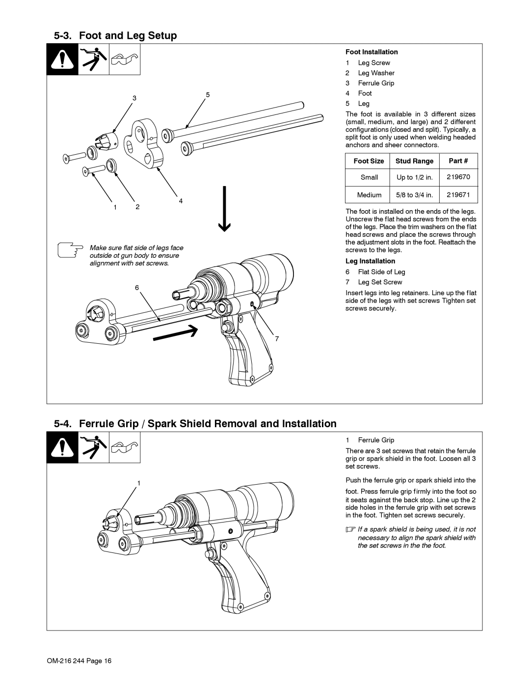
5-3. Foot and Leg Setup
35
Foot Installation
1Leg Screw
2Leg Washer
3Ferrule Grip
4Foot
5Leg
The foot is available in 3 different sizes (small, medium, and large) and 2 different configurations (closed and split). Typically, a split foot is only used when welding headed anchors and sheer connectors.
1 2
4
Foot Size | Stud Range | Part # |
|
|
|
Small | Up to 1/2 in. | 219670 |
|
|
|
Medium | 5/8 to 3/4 in. | 219671 |
|
|
|
The foot is installed on the ends of the legs. Unscrew the flat head screws from the ends of the legs. Place the trim washers on the flat head screws and place the screws through the adjustment slots in the foot. Reattach the
Make sure flat side of legs face outside ot gun body to ensure alignment with set screws.
6
7
screws to the legs.
Leg Installation
6Flat Side of Leg
7Leg Set Screw
Insert legs into leg retainers. Line up the flat side of the legs with set screws Tighten set screws securely.
5-4. Ferrule Grip / Spark Shield Removal and Installation
1 Ferrule Grip
There are 3 set screws that retain the ferrule grip or spark shield in the foot. Loosen all 3 set screws.
1 | Push the ferrule grip or spark shield into the |
|
foot. Press ferrule grip firmly into the foot so
it seats against the back stop. Line up the 2 side holes in the ferrule grip with set screws in the foot. Tighten set screws securely.
. If a spark shield is being used, it is not necessary to align the spark shield with the set screws in the the foot.