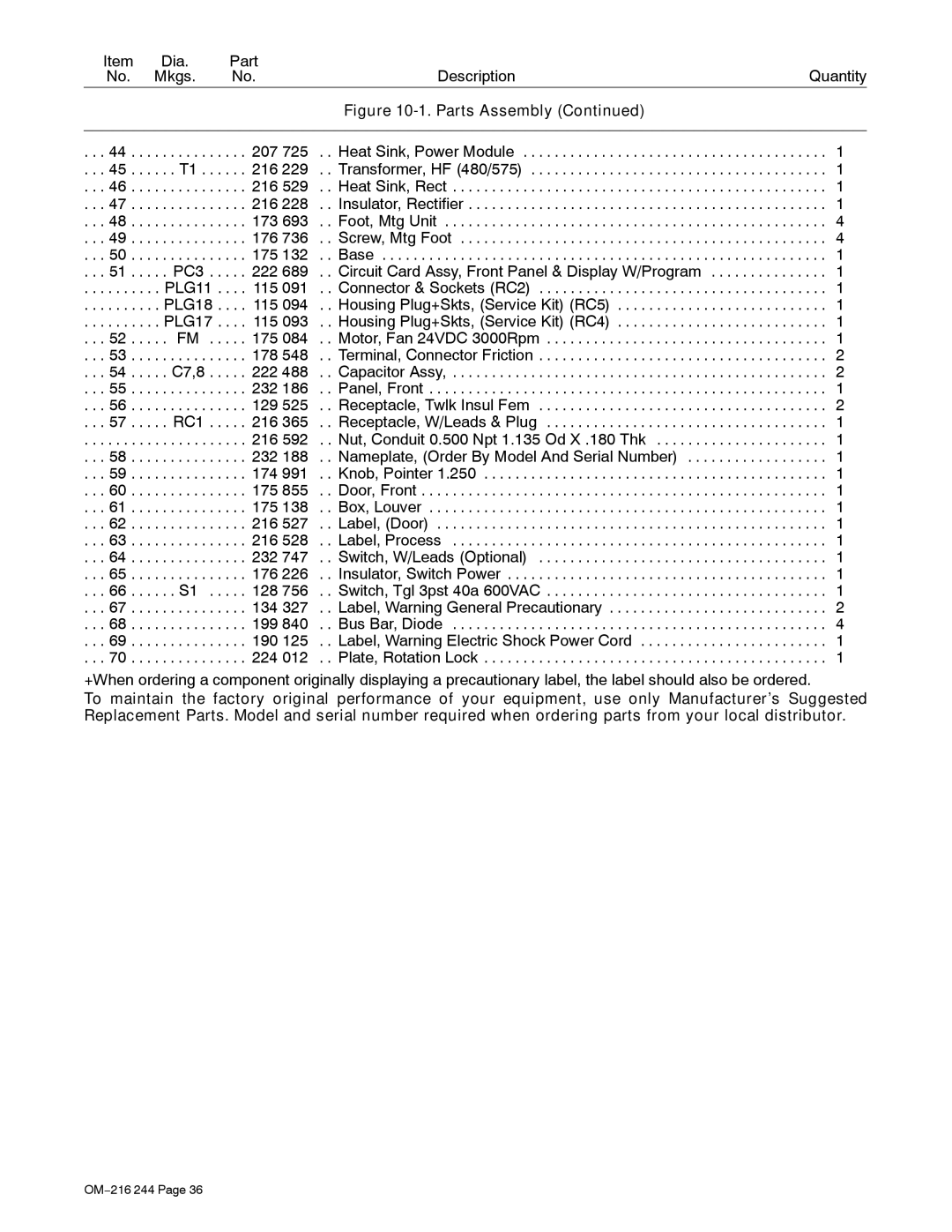
Item | Dia. |
| Part | Description | Quantity |
No. | Mkgs. |
| No. | ||
|
|
|
| Figure |
|
|
|
|
|
|
|
. . . 44 . . . | . . . . . . . | . . . | . . 207 725 | . . Heat Sink, Power Module | . . . 1 |
. . . 45 . . . | . . . T1 . | . . . | . . 216 229 | . . Transformer, HF (480/575) | . . . 1 |
. . . 46 . . . | . . . . . . . | . . . | . . 216 529 | . . Heat Sink, Rect | . . . 1 |
. . . 47 . . . | . . . . . . . | . . . | . . 216 228 | . . Insulator, Rectifier | . . . 1 |
. . . 48 . . . | . . . . . . . | . . . | . . 173 693 | . . Foot, Mtg Unit | . . . 4 |
. . . 49 . . . | . . . . . . . | . . . | . . 176 736 | . . Screw, Mtg Foot | . . . 4 |
. . . 50 . . . | . . . . . . . | . . . | . . 175 132 | . . Base | . . . 1 |
. . . 51 . . . | . . PC3 | . . . | . . 222 689 | . . Circuit Card Assy, Front Panel & Display W/Program | . . . 1 |
. . . . . . . . . | . PLG11 . . | . . 115 091 | . . Connector & Sockets (RC2) | . . . 1 | |
. . . . . . . . . | . PLG18 . . | . . 115 094 | . . Housing Plug+Skts, (Service Kit) (RC5) | . . . 1 | |
. . . . . . . . . | . PLG17 . . | . . 115 093 | . . Housing Plug+Skts, (Service Kit) (RC4) | . . . 1 | |
. . . 52 . . . | . . FM | . . . . . 175 084 | . . Motor, Fan 24VDC 3000Rpm | . . . 1 | |
. . . 53 . . . | . . . . . . . | . . . | . . 178 548 | . . Terminal, Connector Friction | . . . 2 |
. . . 54 . . . | . . C7,8 | . . . | . . 222 488 | . . Capacitor Assy, . . . . . . . . . . . . . . . . . . . . . . . . . . . . . . . . . . . . . . . . . . . . . . . . 2 | |
. . . 55 . . . | . . . . . . . | . . . | . . 232 186 | . . Panel, Front | . . . 1 |
. . . 56 . . . | . . . . . . . | . . . | . . 129 525 | . . Receptacle, Twlk Insul Fem | . . . 2 |
. . . 57 . . . | . . RC1 | . . . | . . 216 365 | . . Receptacle, W/Leads & Plug | . . . 1 |
. . . . . . . . . | . . . . . . . | . . . | . . 216 592 | . . Nut, Conduit 0.500 Npt 1.135 Od X .180 Thk | . . . 1 |
. . . 58 . . . | . . . . . . . | . . . | . . 232 188 | . . Nameplate, (Order By Model And Serial Number) | . . . 1 |
. . . 59 . . . | . . . . . . . | . . . | . . 174 991 | . . Knob, Pointer 1.250 | . . . 1 |
. . . 60 . . . | . . . . . . . | . . . | . . 175 855 | . . Door, Front | . . . 1 |
. . . 61 . . . | . . . . . . . | . . . | . . 175 138 | . . Box, Louver | . . . 1 |
. . . 62 . . . | . . . . . . . | . . . | . . 216 527 | . . Label, (Door) | . . . 1 |
. . . 63 . . . | . . . . . . . | . . . | . . 216 528 | . . Label, Process | . . . 1 |
. . . 64 . . . | . . . . . . . | . . . | . . 232 747 | . . Switch, W/Leads (Optional) | . . . 1 |
. . . 65 . . . | . . . . . . . | . . . | . . 176 226 | . . Insulator, Switch Power | . . . 1 |
. . . 66 . . . | . . . S1 | . . . . . 128 756 | . . Switch, Tgl 3pst 40a 600VAC | . . . 1 | |
. . . 67 . . . | . . . . . . . | . . . | . . 134 327 | . . Label, Warning General Precautionary | . . . 2 |
. . . 68 . . . | . . . . . . . | . . . | . . 199 840 | . . Bus Bar, Diode | . . . 4 |
. . . 69 . . . | . . . . . . . | . . . | . . 190 125 | . . Label, Warning Electric Shock Power Cord | . . . 1 |
. . . 70 . . . | . . . . . . . | . . . | . . 224 012 | . . Plate, Rotation Lock | . . . 1 |
+When ordering a component originally displaying a precautionary label, the label should also be ordered.
To maintain the factory original performance of your equipment, use only Manufacturer’s Suggested Replacement Parts. Model and serial number required when ordering parts from your local distributor.
OM−216 244 Page 36