7-3. Welding Sequence
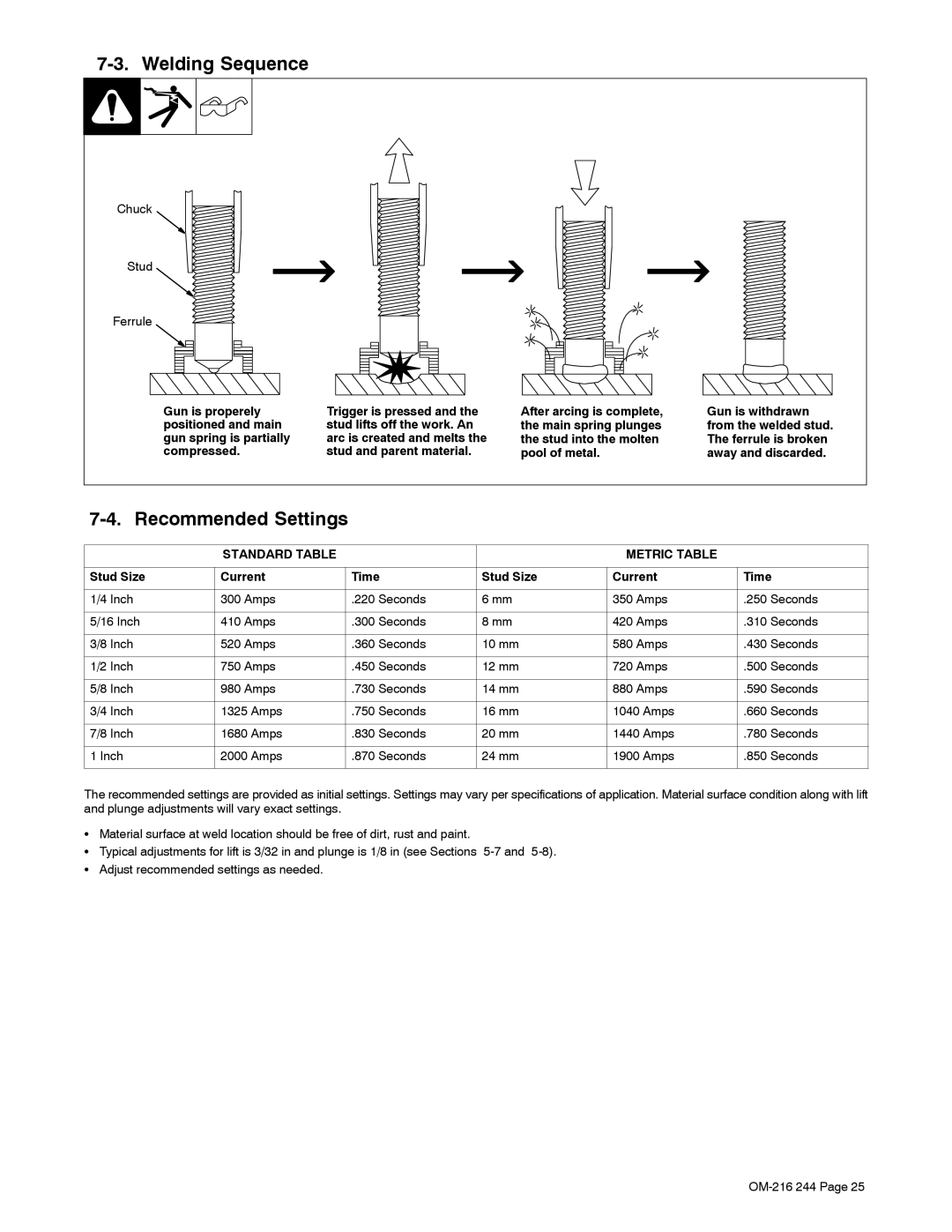
Chuck
Stud
Ferrule
Gun is properely | Trigger is pressed and the | After arcing is complete, |
positioned and main | stud lifts off the work. An | the main spring plunges |
gun spring is partially | arc is created and melts the | the stud into the molten |
compressed. | stud and parent material. | pool of metal. |
Gun is withdrawn from the welded stud. The ferrule is broken away and discarded.
7-4. Recommended Settings
| STANDARD TABLE |
|
| METRIC TABLE |
|
|
|
|
|
|
|
Stud Size | Current | Time | Stud Size | Current | Time |
|
|
|
|
|
|
1/4 Inch | 300 Amps | .220 Seconds | 6 mm | 350 Amps | .250 Seconds |
|
|
|
|
|
|
5/16 Inch | 410 Amps | .300 Seconds | 8 mm | 420 Amps | .310 Seconds |
|
|
|
|
|
|
3/8 Inch | 520 Amps | .360 Seconds | 10 mm | 580 Amps | .430 Seconds |
|
|
|
|
|
|
1/2 Inch | 750 Amps | .450 Seconds | 12 mm | 720 Amps | .500 Seconds |
|
|
|
|
|
|
5/8 Inch | 980 Amps | .730 Seconds | 14 mm | 880 Amps | .590 Seconds |
|
|
|
|
|
|
3/4 Inch | 1325 Amps | .750 Seconds | 16 mm | 1040 Amps | .660 Seconds |
|
|
|
|
|
|
7/8 Inch | 1680 Amps | .830 Seconds | 20 mm | 1440 Amps | .780 Seconds |
|
|
|
|
|
|
1 Inch | 2000 Amps | .870 Seconds | 24 mm | 1900 Amps | .850 Seconds |
|
|
|
|
|
|
The recommended settings are provided as initial settings. Settings may vary per specifications of application. Material surface condition along with lift and plunge adjustments will vary exact settings.
SMaterial surface at weld location should be free of dirt, rust and paint.
STypical adjustments for lift is 3/32 in and plunge is 1/8 in (see Sections
SAdjust recommended settings as needed.