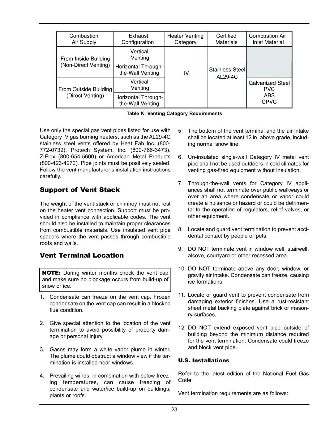
Combustion

Air Supply

Exhaust

Configuration

Heater Venting

Category

Certified Materials

Combustion Air

Inlet Material


Vertical


From Inside Building

Venting


(Non-Direct Venting)

Horizontal Through-


Stainless Steel


the-Wall Venting

IV


AL29-4C


Vertical


From Outside Building

Venting


(Direct Venting)

Horizontal Through-


the-Wall Venting


Table K: Venting


Category Requirements

Galvanized Steel

PVC

ABS

CPVC

Use only the special gas vent pipes listed for use with Category IV gas burning heaters, such as the AL29-4C stainless steel vents offered by Heat Fab Inc. (800- 772-0739), Protech System, Inc. (800-766-3473), Z-Flex (800-654-5600) or American Metal Products (800-423-4270). Pipe joints must be positively sealed. Follow the vent manufacturer’s installation instructions carefully.

Support of Vent Stack

The weight of the vent stack or chimney must not rest on the heater vent connection. Support must be pro- vided in compliance with applicable codes. The vent should also be installed to maintain proper clearances from combustible materials. Use insulated vent pipe spacers where the vent passes through combustible roofs and walls.

Vent Terminal Location

NOTE: During winter months check the vent cap and make sure no blockage occurs from build-up of snow or ice.

1. Condensate can freeze on the vent cap. Frozen condensate on the vent cap can result in a blocked flue condition.

2. Give special attention to the location of the vent termination to avoid possibility of property dam- age or personal injury.

3. Gases may form a white vapor plume in winter. The plume could obstruct a window view if the ter- mination is installed near windows.

4. Prevailing winds, in combination with below-freez- ing temperatures, can cause freezing of condensate and water/ice build-up on buildings, plants or roofs.

5.The bottom of the vent terminal and the air intake shall be located at least 12 in. above grade, includ- ing normal snow line.

6.Un-insulated single-wall Category IV metal vent pipe shall not be used outdoors in cold climates for venting gas-fired equipment without insulation.

7.Through-the-wall vents for Category IV appli- ances shall not terminate over public walkways or over an area where condensate or vapor could create a nuisance or hazard or could be detrimen- tal to the operation of regulators, relief valves, or other equipment.

8.Locate and guard vent termination to prevent acci- dental contact by people or pets.

9.DO NOT terminate vent in window well, stairwell, alcove, courtyard or other recessed area.

10.DO NOT terminate above any door, window, or gravity air intake. Condensate can freeze, causing ice formations.

11.Locate or guard vent to prevent condensate from damaging exterior finishes. Use a rust-resistant sheet metal backing plate against brick or mason- ry surfaces.

12.DO NOT extend exposed vent pipe outside of building beyond the minimum distance required for the vent termination. Condensate could freeze and block vent pipe.

U.S. Installations

Refer to the latest edition of the National Fuel Gas Code.

Vent termination requirements are as follows:

23

Page 23
Image 23
Raypak 503-2003 manual Support of Vent Stack, Vent Terminal Location, Installations

503-2003 specifications

The Raypak 503-2003 is a notable entry in the world of water heating solutions, renowned for its efficiency and reliability in both residential and commercial settings. This model is designed to provide exceptional performance while maintaining ease of use and minimization of environmental impact.

One of the standout features of the Raypak 503-2003 is its advanced heating technology. The unit utilizes a durable, copper heat exchanger which ensures quick and efficient heating of water. This heat exchanger is known for its ability to transfer heat effectively, leading to reduced energy consumption and lower utility bills. The design also allows for a seamless operation, ensuring that the system heats water swiftly without sacrificing performance.

In addition to its efficient heating capabilities, the Raypak 503-2003 is equipped with innovative controls. The digital control panel allows users to easily set and adjust the desired water temperature. This feature provides a level of convenience that simplifies operation while enhancing user experience. Furthermore, the smart technology employed in the unit ensures that it operates within optimal parameters, avoiding unnecessary energy expenditure.

Durability is another hallmark of the Raypak 503-2003. Built with heavy-duty components, this water heating solution is designed to withstand the rigors of continuous use. The rugged construction ensures longevity, making it a cost-effective investment for homeowners and businesses alike. Moreover, the unit is designed to be resistant to corrosion and wear, further extending its lifespan and reliability.

The energy efficiency of the Raypak 503-2003 is a crucial characteristic that sets it apart from competitors. Rated with a high efficiency score, this model contributes to lower emissions and is environmentally friendly. It adheres to various energy standards, making it a suitable choice for those looking to reduce their carbon footprint while enjoying reliable water heating.

Noise reduction is another important feature of the Raypak 503-2003. Designed with quiet operation in mind, the unit operates with minimal noise pollution, allowing for a pleasant environment in both residential and commercial spaces.

In summary, the Raypak 503-2003 combines advanced heating technology, user-friendly controls, durability, and energy efficiency into a robust water heating system. This makes it an excellent choice for those in need of dependable and sustainable heating solutions. Whether for daily home use or for larger commercial applications, the Raypak 503-2003 stands out as a leader in its class.