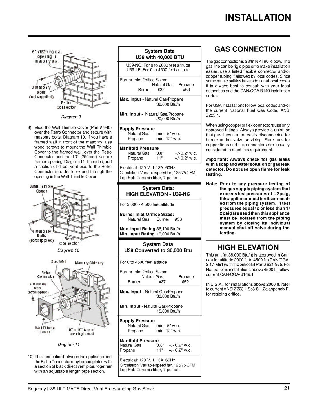
U39-NG, U39-LP specifications
The Regency U39-LP and U39-NG are modern gas fireplaces designed to enhance the aesthetic appeal and functionality of any space while delivering exceptional performance. These units are part of Regency's commitment to innovation and sustainability, providing homeowners with an efficient heating solution that seamlessly integrates into various home styles.One of the standout features of the U39 series is its versatility in fuel options. The U39-LP operates on liquid propane, while the U39-NG utilizes natural gas. This flexibility allows homeowners to choose the best option suited for their existing infrastructure and personal preferences. Both models are designed to deliver efficient heating with an impressive BTU output, ensuring that rooms stay warm and comfortable during colder months.
The U39 series is equipped with cutting-edge technologies, including a state-of-the-art control system that allows users to easily adjust the flame height and heat output. This feature not only enhances user convenience but also promotes energy efficiency by allowing adjustments based on real-time heating needs. The inclusion of an optional remote control further simplifies the operation, enabling users to manage their fireplace from anywhere in the room.
Another remarkable aspect of the Regency U39-LP and U39-NG is the clean, contemporary design. The linear shape and large viewing area provide an unobstructed view of the flames, adding a stunning focal point to any living space. The customizable options for finishes and surround materials mean that homeowners can tailor the fireplace to perfectly match their décor, whether it be modern, traditional, or somewhere in between.
Safety is a top priority for Regency, and the U39 series includes multiple safety features to ensure peace of mind. An integrated safety shut-off system is designed to automatically turn off the unit in case of emergencies, while tempered glass doors protect against accidental burns.
In summary, the Regency U39-LP and U39-NG gas fireplaces embody a blend of functionality, beauty, and safety. With their high thermal efficiency, user-friendly technologies, and elegant design, these fireplaces are an ideal choice for anyone looking to elevate their home heating experience while enjoying the charm of a glowing fire. Whether it's for a cozy gathering with family or a quiet evening alone, the U39 series stands out as a stylish solution with exceptional performance.

