OWNER’S MANUAL
ELECTRIC CHAIN SAW
MODELS M15012US, M15014AS, M30016US, M30016AS M30016AW, M35016AW
GUARDE ESTAS INSTRUCCIONES
Keep your purchase receipt for warranty coverage
Conservez votre reçu d’achat pour obtenir le service sous garantie
CONSERVER CES DIRECTIVES
CONTENTS
ENGLISH
BEFORE OPERATING SAW
IMPORTANT SAFETY INFORMATION
WHILE OPERATING SAW
IMPORTANT SAFETY INFORMATION
Kickback Safety Devices On This Saw
KICKBACK
ENGLISH
Save these instructions
Saw Maintenance and Kickback Safety
MAINTENANCE AND STORAGE OF CHAIN SAW
UNPACKING
Models M15012US, M15014AS, M30016US, M30016AS
PRODUCT IDENTIFICATION
ENGLISH
Models M30016AW, M35016AW
CHAIN SAW NAMES AND TERMS
Power Cord Cord Hitch Slot Extension Cord
QUICK START GUIDE
ENGLISH
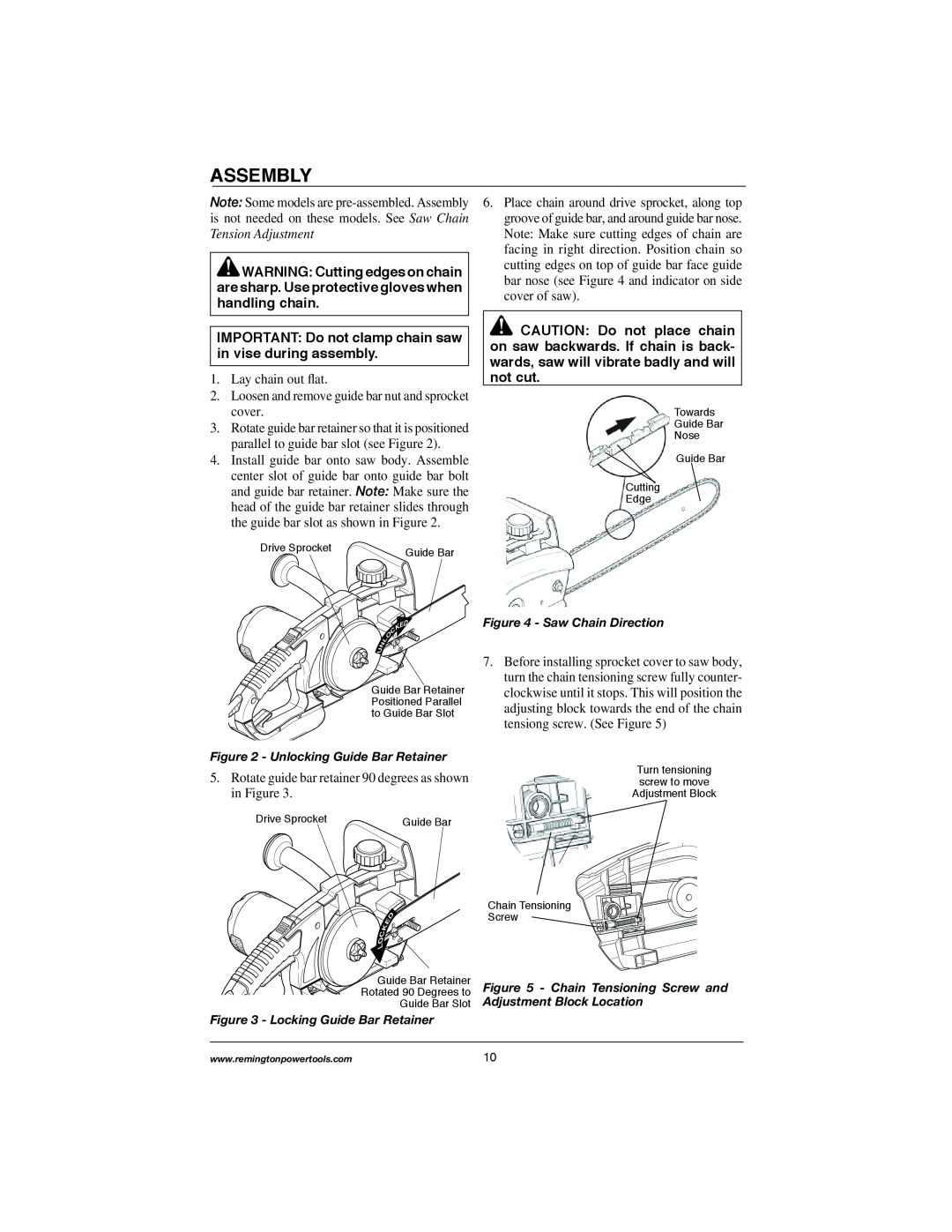
ASSEMBLY
ENGLISH
ASSEMBLY
12. Retighten the bar nut finger tight
SAW CHAIN TENSION ADJUSTMENT
OILING CHAIN Manual Oil System
OPERATING CHAIN SAW
FILLING OIL TANK
CLEARING SPROCKET COVER OF DEBRIS
EXTENSION CORDS
CUTTING WITH THE CHAIN SAW
B Felling Cut
Felling Procedure A Felling Notch
Before Felling a Tree
OPERATING CHAIN SAW
Entire Length Of Log On Ground
LIMBING A TREE
BUCKING A LOG
OPERATING CHAIN SAW
TRIMMING A TREE Pruning
Log Supported On One End
Log Supported On Both Ends
OPERATING CHAIN SAW
SHARPENING SAW CHAIN
CLEANING AND MAINTENANCE
Normal Guide Bar Maintenance
CARE OF GUIDE BAR
Filing Cutter Depth Gauges
Items Needed to Sharpen Chain
Sharpening Cutters
Replacing Saw Chain
REPAIR SERVICE
REPLACEMENT CHAINS
REPLACEMENT PARTS AND ACCESSORIES
Warranty Service
OBSERVED FAULT
TROUBLESHOOTING
TECHNICAL SERVICE
POSSIBLE CAUSE
NEW PRODUCTS Standard Warranty
WARRANTY INFORMATION
REMINGTON BRAND ELECTRIC CHAIN SAW LIMITED WARRANTIES
FACTORY RECONDITIONED PRODUCTS Limited Warranty
ESPAÑOL
SIERRA ELÉCTRICA
MANUAL PARA EL USUARIO
MODELOS M15012US, M15014AS, M30016US, M30016AS M30016AW, M35016AW
EL CONTENIDO
ANTES DE UTILIZAR LA SIERRA
INFORMACIÓN IMPORTANTE DE SEGURIDAD
ESPAÑOL
AL UTILIZAR LA SIERRA
INFORMACIÓN IMPORTANTE DE SEGURIDAD
plomo de las pinturas hechas a base de plomo
Dispositivos de seguridad de esta sierra contra contragolpes
INFORMACIÓN IMPORTANTE DE SEGURIDAD
ESPAÑOL
Mantenimiento de la cadena y seguridad contra contragolpes
INFORMACIÓN IMPORTANTE DE SEGURIDAD
DESEMBALAJE
GUARDE ESTAS INSTRUCCIONES
MANTENIMIENTO Y ALMACENAMIENTO DE SU SIERRA ELÉCTRICA
Modelos M15012US, M15014AS, M30016US, M30016AS
IDENTIFICACIÓN DEL PRODUCTO
ESPAÑOL
Modelos M30016AW, M35016AW
TERMINOLOGÍA
Botón de cierre del interruptor Gatillo
GUÍA RÁPIDA DE ARRANQUE
ESPAÑOL
Enganche para el cable
ENSAMBLAJE
11. Deslice lentamente la barra guía hacia el
Tensión de la Cadena de la Sierra
ENSAMBLAJE
cuerpo de la sierra hasta que el bloque de
AJUSTE DE TENSIÓN DE LA CADENA SERRADA
Barra Guía
LUBRICACIÓN
USO DE LA SIERRA ELÉCTRICA
ESPAÑOL
LUBRICACIÓN DE LA CADENA
Modelos M30016US, M30016AS, M30016AW, M35016AW
USO DE LA SIERRA ELÉCTRICA
Modelos M15012US, M15014AS
Cable de alimentación Enganche para el cable Cable de prolongación
ESPAÑOL
USO DE LA SIERRA ELÉCTRICA
TALA DE UN ÁRBOL Derribamiento de un árbol ADVERTENCIA
B Tala final
USO DE LA SIERRA ELÉCTRICA
DESMEMBRAMIENTO DE UN ÁRBOL
La totalidad del tronco sobre el suelo
USO DE LA SIERRA ELÉCTRICA
ESPAÑOL
Figura 16 - Trozado del tronco completamente apoyado en el suelo
ADVERTENCIA No utilice la sie- rra eléctrica mientras se encuentre
USO DE LA SIERRA ELÉCTRICA
PODA DE UN ÁRBOL
arriba de un árbol
LIMPIEZA Y MANTENIMIENTO
ESPAÑOL
Elementos necesarios para afilar la cadena
AFILADO DE LA CADENA
LIMPIEZA Y MANTENIMIENTO
Afilado de los elementos de corte
Limado de los calibradores de medida de profundidad
ALMACENAMIENTO
LIMPIEZA Y MANTENIMIENTO
Cadenas de repuesto
SERVICIO TÉCNICO
SERVICIO DE REPARACIÓN
ACCESORIOS Y PIEZAS DE REPUESTO
OBSERVADA
DIAGNÓSTICO Y RESOLUCIÓN DE PROBLEMAS
FALLA
CAUSA POSIBLE
NUEVOS PRODUCTOS Garantía Estándar
INFORMACIÓN DE GARANTÍA
SIERRA ELÉCTRICA DE LA MARCA DE REMINGTON GARANTÍAS LIMITADAS
PRODUCTOS RECONDICIONADOS EN FÁBRICA Garantía Limitada
MODÈLES M15012US, M15014AS, M30016US, M30016AS M30016AW, M35016AW
TRONÇONNEUSE ÉLECTRIQUE PRIME
FRANÇAIS
MANUEL D’UTILISATION ET D’ENTRETIEN
CONTENUS
PENDANT LUTILISATION DE LA TRONÇONNEUSE
CONSIGNES DE SÉCURITÉ IMPORTANTES
AVANT D’UTILISER LA TRONÇONNEUSE
FRANÇAIS
CONSIGNES DE SÉCURITÉ IMPORTANTES
le plomb contenu dans les peintures à base de plomb
CONSIGNES DE SÉCURITÉ IMPORTANTES
RECUL
Entretien de la tronçonneuse et protection contre le recul
FRANÇAIS
CONSERVER CES DIRECTIVES
DÉBALLAGE
ENTRETIEN ET REMISAGE DE LA TRONÇONNEUSE
CONSIGNES DE SÉCURITÉ IMPORTANTES
Modèles M15012US, M15014AS, M30016US, M30016AS
IDENTIFICATION DU PRODUIT
FRANÇAIS
Modèles M30016AW, M35016AW
VOCABULAIRE DE LA TRONÇONNEUSE
FRANÇAIS
GUIDE DE DÉMARRAGE RAPIDE
fixer. Voir Rallonges Électriques pour
MONTAGE
FRANÇAIS
MONTAGE
12. Resserrez l’écrou du guide-chaîne à la main
RÉGLAGE DE LA TENSION DE LA CHAÎNE
LUBRIFICATION DE LA CHAÎNE
UTILISATION DE LA TRONÇONNEUSE
REMPLISSAGE DU RÉSERVOIR D’HUILE
NETTOYAGE DES DÉBRIS DU COUVERCLE DU PIGNON
UTILISATION DE LA TRONÇONNEUSE
RALLONGES ÉLECTRIQUES
SCIAGE AVEC LA TRONÇONNEUSE
Longueur du
Procédure d’abattage A Sifflet d’abattage
ABATTAGE D’UN ARBRE
Avant d’abattre un arbre
UTILISATION DE LA TRONÇONNEUSE
UTILISATION DE LA TRONÇONNEUSE
B Trait d’abattage
ÉBRANCHAGE
3. Enlever le morceau de tronc créé par les deux entailles
La bille est soutenue à une extrémité
TRONÇONNAGE D’UNE BILLE
Toute la bille repose au sol
UTILISATION DE LA TRONÇONNEUSE
TAILLE D’UN ARBRE Élagage
RECUL
La bille est soutenue aux deux extrémités
UTILISATION DE LA TRONÇONNEUSE
ENTRETIEN DE LA GUIDE-CHAÎNE
NETTOYAGE ET ENTRETIEN
NETTOYAGE DU CARTER DE TRONÇONNEUSE
FRANÇAIS
Affûtage des taillants
AFFÛTAGE DE LA CHAÎNE
Outils nécessaires pour affûter la chaîne
NETTOYAGE ET ENTRETIEN
CHAÎNES DE RECHANGE
REMPLACEMENT DE LA CHAÎNE
Pièces de Rechange et Accessoires
Limage des limiteurs de profondeur
SERVICE DE RÉPARATION
SERVICE TECHNIQUE
PIÈCES DE RECHANGE ET ACCESSOIRES
Service sous garantie
OBSERVÉE
DÉPANNAGE
DÉFAILLANCE
CAUSE POSSIBLE
PRODUITS NEUFS Garantie standard
INFORMATION SUR LA GARANTIE
TRONÇONNEUSE ÉLECTRIQUE DE MARQUE DE REMINGTON GARANTIES LIMITÉES
PRODUITS REMIS À NEUF À L’USINE Garantie limitée
Notes/Notas/Remarques
Page
PARTS LIST/LISTA DE REPUESTOS/LISTE DES PIÈCES
Tool & Equipment
PARTS CENTRAL/CENTRAL DE PIEZAS/DÉPÔT DE PIÈCES
Ray’s Portable Heater Service
Bernies Tools & Fasteners
Page
113005-01 Rev.G
03/08