Manuals
/
Rinnai
/
Household Appliance
/
Furnace
Rinnai
RHFE-431WTA installation manual Parts List
Models:
RHFE-431WTA
1
52
64
64
Download
64 pages
61.41 Kb
49
50
51
52
53
54
55
56
<
>
Troubleshooting
Specs
Install
Parts list
Error codes
Cut-Awaydiagram
Warranty
Dimension
Maintenance
Fault-FailureProcedure
Page 52
Image 52
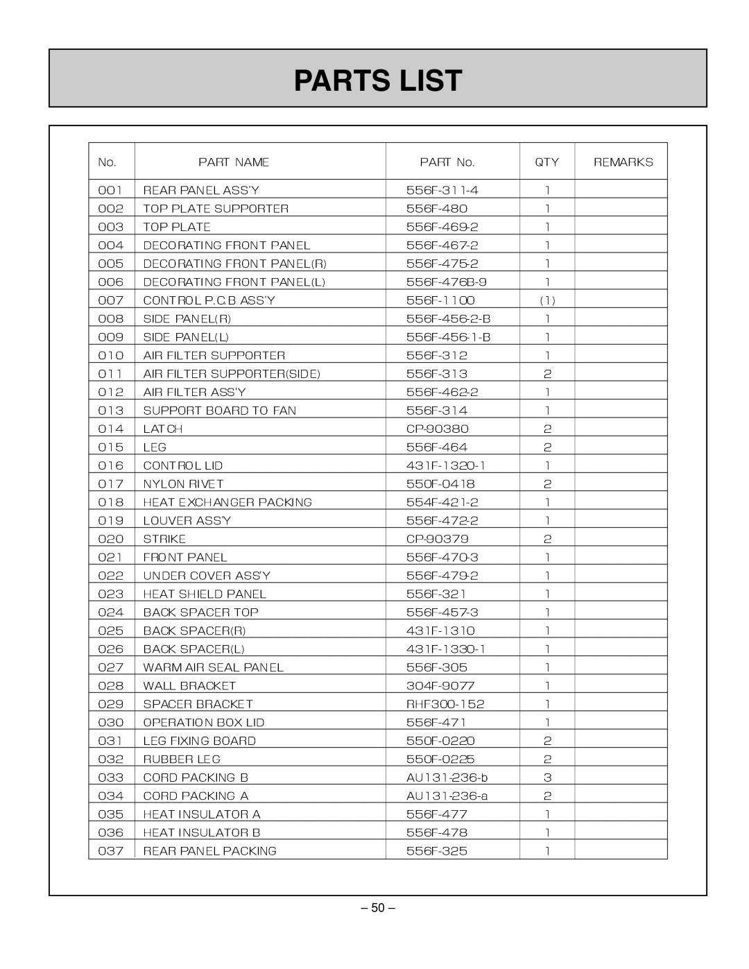
PARTS LIST
– 50 –
Page 51
Page 53
Page 52
Image 52
Page 51
Page 53
Contents
Owner’s Operation and Installation Manual
HOME OWNER / INSTALLER FOR YOUR SAFETY
RHFE-431WTA
ENERGYSAVER GAS DIRECT VENT WALL FURNACE
Table of Contents
ENERGYSAVER RHFE-431WTA
FEATURES OF THE RHFE-431WTAUNITS
SAFETY DEVICES
TECHNICAL DATA
IMPORTANT POINTS / USAGE AND INSTALLATION MUSTS
GAS CONVERSION SPECIFICATIONS
Included in Carton
4.This appliance is not designed to be built in
DIMENSIONS
MUST BE INSTALLED ACCORDING TO THESE INSTRUCTIONS
ALTERATION OF THE ORIGINAL DESIGN INSTALLED OTHER
THIS SERIES HEATER IS DESIGN CERTIFIED BY CSA
SPECIFICATIONS
SPECIFICATIONS
Safety Devices
Power failure - PCB
Power surge - 3 Amp. fuse
Fan delay - Micro computer timer
SAFETY POINTS
SAFETY POINTS
Keep flammable materials, trees, shrubs
GETTING TO KNOW YOUR NEW RHFE-431
CONTROL PANEL
LED DISPLAY
Temperatures
MODE
CUT-AWAYDIAGRAM
NOTICE BEFORE INSTALLATION
INSTALLATION INSTRUCTIONS
GAS CONNECTION
VENT LOCATION
FITTING TOP SPACER + WALL CLIP
FLUE MANIFOLD POSITION
SECURE HEATER TO WALL
VENT TERMINATION CLEARANCES
U.S.Installations1foot
3feet
10feet
LOCATION / CLEARANCES
SNOW AREAS
STANDARD INSTALLATION OF FLUE MANIFOLD
FIT BACK COVERS SIDES ONLY
SLEEVE AND MANIFOLD INSTALLATION
METHOD FOR STANDARD WALLS
5. Check rubber seal is in place on terminal
AIR INLET HOSE
FITTING UNIT
LOCKING CLAMP SCREW CLAMP AND INSULATION
INSTRUCT CUSTOMER ON USE OF HEATER
FOR YOUR SAFETY READ BEFORE OPERATING
OPERATING INSTRUCTION LABEL
ENERGYSAVER RHFE-431WTA
OPERATING INSTRUCTIONS
SETTING THE CURRENT TIME & DAY
SETTING THE CLOCK
TO OPEN THE CONTROL PANEL
To turn the heater ON
OPERATING THE HEATER MANUALLY
To turn the heater OFF
LOW 76F
5 30am
8 00am
9 30pm
PROGRAMING THE WEEKLY TIMERS
Mo Tu We Th Fr Sa Su
1 2 3 4 OFF
Auto Frost Man Override Select Progr Clock Temp R
PROGRAMING THE TIMERS EXAMPLE
EXAMPLE SCHEDULE
PROGRAMING THE TIMERS EXAMPLE cont
THE TIMERS”
To enter the Weekly Timer Review mode
WEEKLY TIMER REVIEW FUNCTION
To exit the Weekly Timer Review mode
YOUR WEEKLY TIMER PROGRAM
FACTORY PRE-SETPROGRAM
Points to remember when writing your program
Points to consider before writing your program
RETURNING TO MANUAL MODE
OPERATING THE TIMERS
Follow the steps below to operate the timers
OVERRIDE FUNCTION
If the current timer
To turn on the Override function
period is ON heating
FROST PROTECTION
To turn off the Frost Protection
ENERGY SAVING MODE
To turn on the Economy mode
To turn off the Economy Mode
Economy Mode Information
To activate the Function Lock
FUNCTION LOCK
To deactivate the Function Lock
TESTING
CHECK
Testing Unit
Fault-FailureProcedure
PRE-SERVICECHECK
When the unit is turned off
At Ignition
During Combustion
TROUBLE SHOOTING
ERROR MESSAGES
agent and arrange for a service call
FAULT
CODE DISPLAYED
MAINTENANCE / SERVICE
MAINTENANCE SUGGESTIONS
VISUAL CHECK
SATISFACTORY
WIRING DIAGRAM
Warranty Information
Limited Warranty
CONSUMER SUPPORT
What is covered?
Limited Warranty - continued
How do I get service?
What is not covered?
What will Rinnai do?
SCHEMATIC DIAGRAM
– 45 –
Page
Page
Page
Page
PARTS LIST
Page
Page
Page
Page
FLOW DIAGRAM
Vent sizes
NAMES AND NUMBERS OF PARTS
HOW TO INSTALL
TYPES COMPATIBLE WITH EXTENSION SET
INSTALLING AN EXTENSION KIT
1. How to connect exhaust pipes
CAUTIONS
2. How to connect air intake hose
3. Affixing the air intake hose and exhaust pipe
1.Maximum extendable length
QUALIFIED INSTALLING AGENCY
Page
431F-1720×0800
2008.09
103 International Drive Peachtree City, Georgia
Phone 1-800-621-9419 Fax