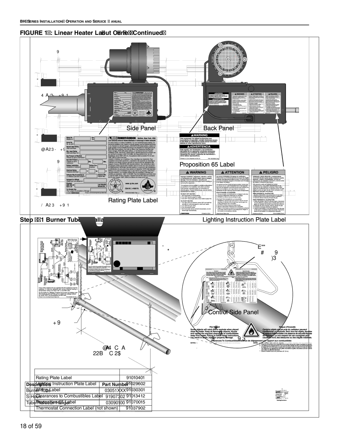
FIGURE 17: Linear Heater Layout Overview (Continued)
| bc |
|
|
|
|
|
|
|
g | d | e | e | e | e | e |
|
|
f |
|
|
|
|
|
|
|
|
60' (18.3 m) Tube Length |
|
|
|
|
|
|
| |
| bc |
|
|
|
|
|
|
|
g | d | e | e | e | e | e | e |
|
f |
|
|
|
|
|
|
|
|
70' (21. 3 m) Tube Length |
|
|
|
|
|
|
| |
| bc |
|
|
|
|
|
|
|
g | d | e | e | e | e | e | e | e |
f |
|
|
|
|
|
|
|
|
80' (24.4 m) Tube Length |
|
|
|
|
|
|
| |
Step 6.1 Burner Tube Installation
NOTE:
Tubing requires a downward slope of 1/2" (13 mm)
per 20' (6 m) away from burner.
Hanger ![]()
![]()
![]()
Burner Tube
7' 6" ± 1'
(229 cm ± 25 cm)
Offset mounting hole must be ![]() to the top.
to the top.
Weld seam must be to the bottom of the tube.
Description | Part Number |
Burner Tube | 03051XXX |
|
|
91907302 | |
|
|
Tube/Reflector Hanger | 03090100 |
|
|
18 of 59