Manuals
/
Roberts Gorden
/
Household Appliance
/
Electric Heater
Roberts Gorden
BH-125, BH-60, BH-40, BH-150, BH-175, BH-115, BH-100 Manifold Gas Pressure Setting
Models:
BH-125
BH-80
BH-200
BH-140
BH-100
BH-115
BH-175
BH-150
BH-40
BH-60
1
59
70
70
Download
70 pages
6.75 Kb
56
57
58
59
60
61
62
63
Troubleshooting
Specifications
Install
Wiring
Warranty
Maintenance
Optional Heater Accessories
Coupling and Tube Assembly
Manifold Gas Pressure Setting
How to
Page 59
Image 59
SECTION 12: T
ROUBLESHOOTING
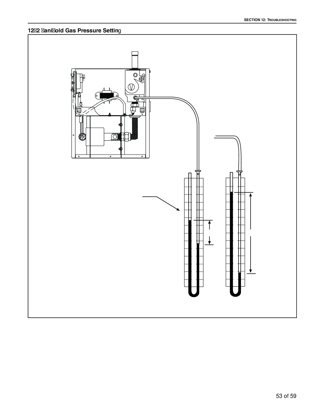
12.2 Manifold Gas Pressure Setting
53 of 59
Page 58
Page 60
Page 59
Image 59
Page 58
Page 60
Contents
Economical Unitary
Page
Roberts-Gordon LLC
Page
Table of Figures
Page
California Proposition
Heater Safety
Manpower Requirements
Safety Labels and Their Placement
Description
Top and Bottom Panel Label Placement
Description Part Number
Side and Back Panel Label Placement
National Standards and Applicable Codes
Installer Responsibility
Wall Tag
Clearances are the required distances that
Maintain clearances to combustibles at all times for safety
Centimeters
Inches
C D
Tube, Standard Reflector Model
45 Tilt Reflector Model
Inches Centimeters
Tube, Opposite 45 Reflector Model
Vented
Unvented
National Standards and Applicable Codes
Reflector End Cap
Major Components
Stainless Steel
Burner Tube
Contents of BH-Series Burner Carton
Standard Parts List
Core Packages Minimum Standard Aluminized
Heater Installation
Run Length Typical Expansion
Critical Hanger Placement
Linear Heater Assembly Overview
Linear Heater Layout Overview
Linear Heater Layout Overview
Burner Tube Installation
Tube Clamp Package
Tube Clamp Package Installation
Coupling and Tube Assembly
Model
1 Coupling and Tube Assembly
2 Coupling and Tube Assembly
Tube Length
Turbulator Installation
Turbulator Installation
Hanger Burner Tube Reflector
Description Part Number Reflector Support Package
1 Reflector, U-Clip and Reflector Support Installation
Burner Installation
Optional Heater Accessories
Tube Heater Assembly Overview
Tube Heater Layout Overview
Clip Package
Elbow Package Configuration .2.1 Elbow Installation
Between Burner and Elbow
Elbow Package
2 Elbow Installation
Reflector Joint Detail
5 Reflector Joint Detail
2 Side Reflector Installation
Reflector Side Extension 1 Bracket Installation
Description Part Number Lower Clearance Shield Package
Description Part Number Reflector Side Extension 01370412
2 Frame Shield Installation
Distance a Extension
3 Grille Installation
2 Grille End Cap Installation
Canadian Requirements
Venting
United States Requirements
Unvented Operation Tube Termination
Unvented Operation
Horizontal Venting
Vertical Venting
Common Side Wall Venting
Vertical Ventilation 4 10 cm Pipe
Common Vertical Venting
Description Part Number Vent Cap 4 10 cm 90502300
Vertical Outside Air Supply for Single Heater Installation
Outside Combustion Air Supply
Description Part Number Vent Cap 6 15 cm 90502302
Vertical Outside Air Supply for Double Heater Installation
GAS Piping
Failure to follow these instructions can result
When attaching gas hose
Correct Positions
Hold gas nipple securely with pipe wrench
Line Voltage Thermostat Wiring
Wiring
Front View
Low Voltage Thermostat Wiring
Internal Wiring
Ladder Diagram Electrical Connection to the Burner
To Shut Off Heater
Operation and Maintenance
Pre-Season Maintenance and Annual Inspection
Sequence of Operation
Reflector
Vicinity of the Heater
Vehicles and Other
Objects
Electrode
Safety Labels
Blower Scroll, Wheel
Motor Burner Cup and Orifice
Troubleshooting
YES
Troubleshooting Flow Chart
Page
Manifold Gas Pressure Setting
Replacement Parts
Replacement Parts
Description Part Number
Pipe Connection
General Specifications
Dimensions
GAS Pressure AT Manifold
Page
Limitations on Authority Representatives
Warranty is Void if
ROBERTS-GORDON LLC will PAY for
ROBERTS-GORDON LLC will not PAY for
Page
Page
Page
Top
Page
Image
Contents