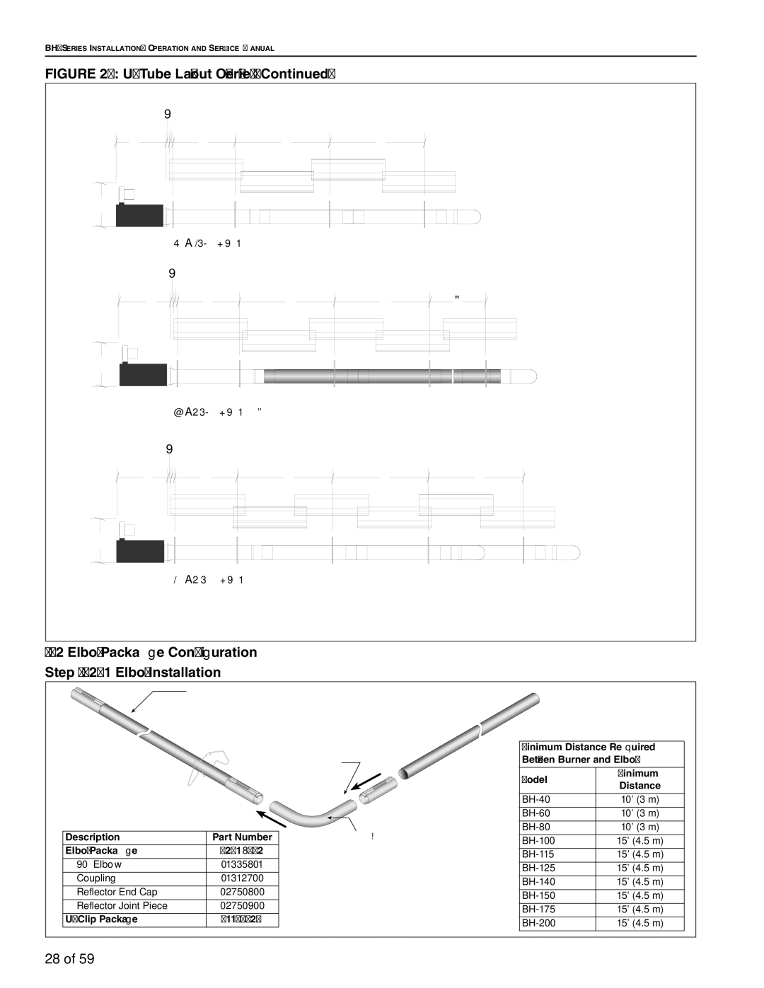
FIGURE 20: U-Tube Layout Overview (Continued)
| bc |
|
|
|
g | d | e | e |
|
h |
|
|
|
|
| 60' (18.3 m) Tube Length |
|
| |
| bc |
|
|
|
g | d | e | e | f |
h |
|
|
|
|
| 70' (21.3 m) Tube Length** |
|
| |
| bc |
|
|
|
g | d | e | e | e |
h |
|
|
|
|
| 80' (24.4 m) Tube Length |
|
| |
7.2Elbow Package Configuration Step 7.2.1 Elbow Installation
| Tube |
|
|
| |
|
|
| Minimum Distance Required | ||
| Coupling |
| Between Burner and Elbow | ||
|
|
| Model | Minimum | |
|
|
| Distance | ||
|
|
|
| ||
|
|
| 10' (3 m) | ||
|
|
| 10' (3 m) | ||
Description | Part Number | 90° Elbow | 10' (3 m) | ||
15' (4.5 m) | |||||
Elbow Package | 02718702 |
| |||
| 15' (4.5 m) | ||||
90° Elbow | 01335801 |
| |||
| 15' (4.5 m) | ||||
Coupling | 01312700 |
| |||
| 15' (4.5 m) | ||||
Reflector End Cap | 02750800 |
| |||
| 15' (4.5 m) | ||||
Reflector Joint Piece | 02750900 |
| |||
| 15' (4.5 m) | ||||
| 91107720 |
| |||
| 15' (4.5 m) | ||||
|
|
| |||
28 of 59 |
|
|
|
| |