BLACKHEAT® INSTALLATION OPERATION AND SERVICE MANUAL
Step 7.4.1 Coupling and Tube Assembly (Continued)
![]() WARNING
WARNING
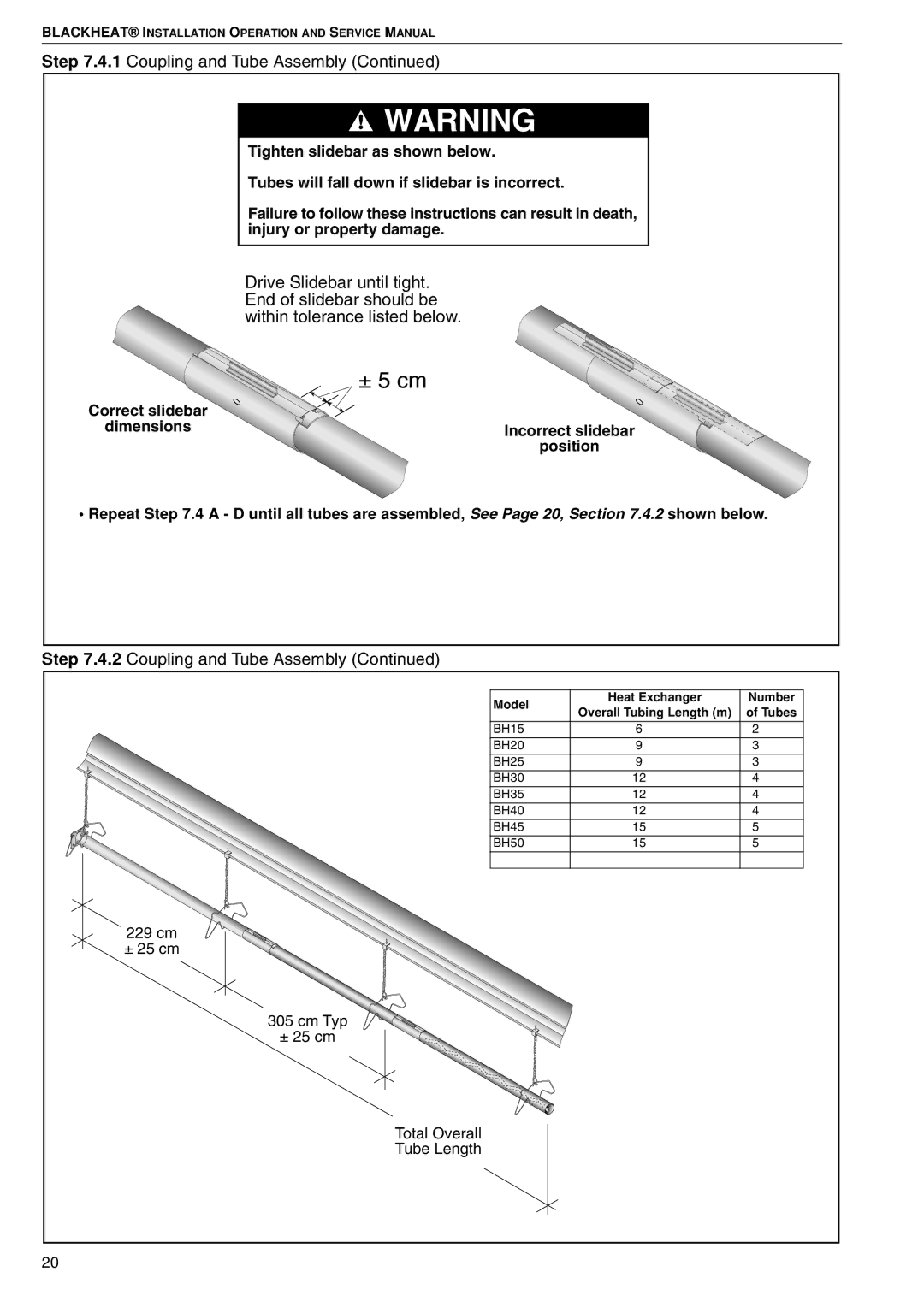
Tighten slidebar as shown below.
Tubes will fall down if slidebar is incorrect.
Failure to follow these instructions can result in death, injury or property damage.
Drive Slidebar until tight. End of slidebar should be within tolerance listed below.
± 5 cm
Correct slidebar
dimensions
Incorrect slidebar
position
•Repeat Step 7.4 A - D until all tubes are assembled, See Page 20, Section 7.4.2 shown below.
Step 7.4.2 Coupling and Tube Assembly (Continued)
Model | Heat Exchanger | Number | |
Overall Tubing Length (m) | of Tubes | ||
| |||
BH15 | 6 | 2 | |
BH20 | 9 | 3 | |
BH25 | 9 | 3 | |
BH30 | 12 | 4 | |
BH35 | 12 | 4 | |
BH40 | 12 | 4 | |
BH45 | 15 | 5 | |
BH50 | 15 | 5 | |
229 cm |
|
| |
± 25 cm |
|
| |
305 cm Typ |
|
| |
± 25 cm |
|
| |
Total Overall |
|
| |
Tube Length |
|
| |
20 |
|
|