SECTION 3: CRITICAL CONSIDERATIONS
NOTE: 1. All dimensions are from the Tube surface.
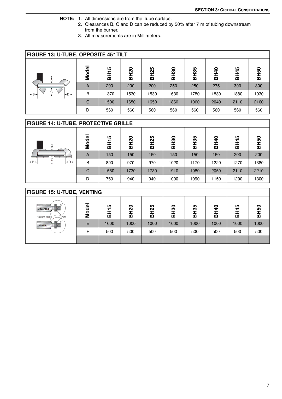
2.Clearances B, C and D can be reduced by 50% after 7 m of tubing downstream from the burner.
3.All measurements are in Millimeters.
FIGURE 13: U-TUBE, OPPOSITE 45° TILT
| A |
|
B | C | D |
|
Model A B C
D
BH15
200
1370
1500
560
BH20
200
1530
1650
560
BH25
200
1530
1650
560
BH30
250
1630
1860
560
BH35
250
1780
1960
560
BH40
275
1830
2040
560
BH45
300
1880
2110
560
BH50
300
1930
2160
560
FIGURE 14: U-TUBE, PROTECTIVE GRILLE
| A |
| Model |
|
|
| |
|
|
| A |
B | C | D | B |
|
C
D
BH15
150
890
1580
760
BH20
150
970
1730
940
BH25
150
970
1730
940
BH30
150
1020
1910
1000
BH35
150
1170
1980
1090
BH40
150
1220
2050
1150
BH45
200
1270
2110
1200
BH50
200
1380
2210
1300
FIGURE 15: U-TUBE, VENTING
Radiant tubes | Fan | Model | BH15 | BH20 |
| E |
|
|
|
Unvented |
|
|
|
|
| F | E | 1000 | 1000 |
Vented |
| |||
|
|
|
| |
|
| F | 500 | 500 |
BH25 | BH30 | BH35 | BH40 | BH45 | BH50 |
|
|
|
|
|
|
1000 | 1000 | 1000 | 1000 | 1000 | 1000 |
500 | 500 | 500 | 500 | 500 | 500 |
|
|
|
|
|
|
|
|
|
|
|
|
7