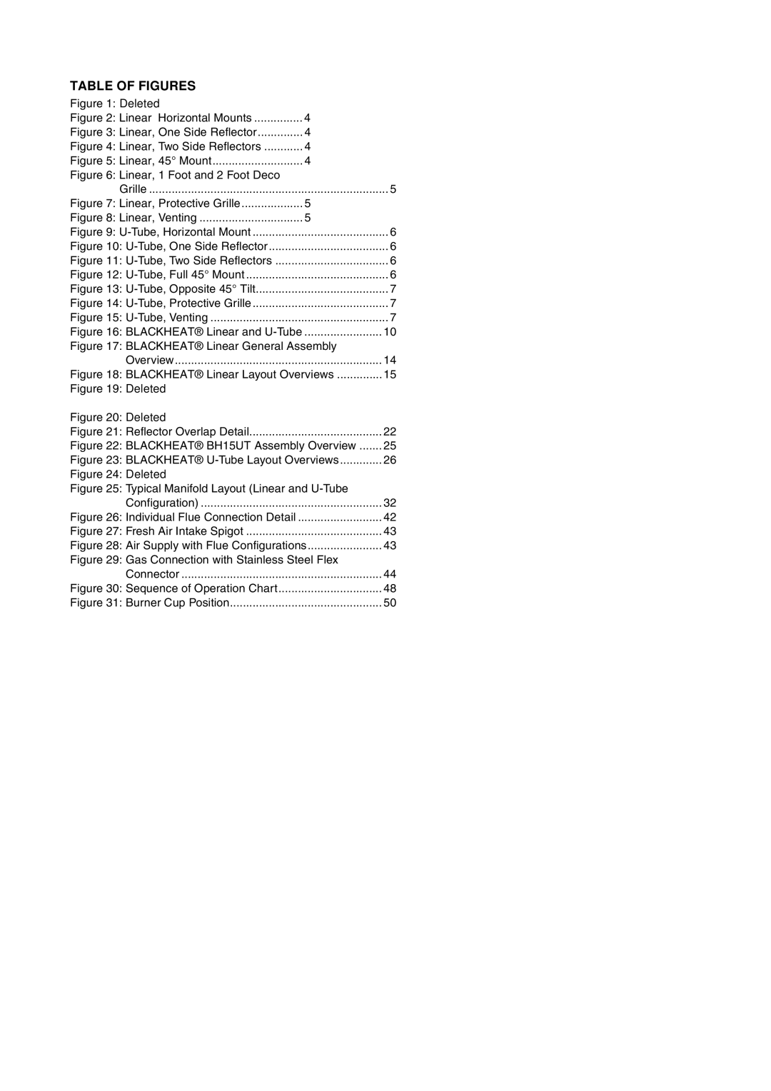
TABLE OF FIGURES
Figure 1: Deleted |
|
|
Figure 2: Linear Horizontal Mounts | 4 |
|
Figure 3: Linear, One Side Reflector | 4 |
|
Figure 4: Linear, Two Side Reflectors | 4 |
|
Figure 5: Linear, 45° Mount | 4 |
|
Figure 6: Linear, 1 Foot and 2 Foot Deco |
|
|
Grille | 5 | |
Figure 7: Linear, Protective Grille | 5 |
|
Figure 8: Linear, Venting | 5 |
|
Figure 9: | 6 | |
Figure 10: | 6 | |
Figure 11: | 6 | |
Figure 12: | 6 | |
Figure 13: | 7 | |
Figure 14: | 7 | |
Figure 15: | 7 | |
Figure 16: BLACKHEAT® Linear and | ........................ | 10 |
Figure 17: BLACKHEAT® Linear General Assembly |
| |
Overview | 14 | |
Figure 18: BLACKHEAT® Linear Layout Overviews | 15 | |
Figure 19: Deleted |
|
|
Figure 20: Deleted |
|
|
Figure 21: Reflector Overlap Detail | 22 | |
Figure 22: BLACKHEAT® BH15UT Assembly Overview | 25 | |
Figure 23: BLACKHEAT® | 26 | |
Figure 24: Deleted |
|
|
Figure 25: Typical Manifold Layout (Linear and |
| |
Configuration) | 32 | |
Figure 26: Individual Flue Connection Detail | 42 | |
Figure 27: Fresh Air Intake Spigot | 43 | |
Figure 28: Air Supply with Flue Configurations | 43 | |
Figure 29: Gas Connection with Stainless Steel Flex |
| |
Connector | 44 | |
Figure 30: Sequence of Operation Chart | 48 | |
Figure 31: Burner Cup Position | 50 | |
