No
BLACKHEAT® INSTALLATION OPERATION AND SERVICE MANUAL
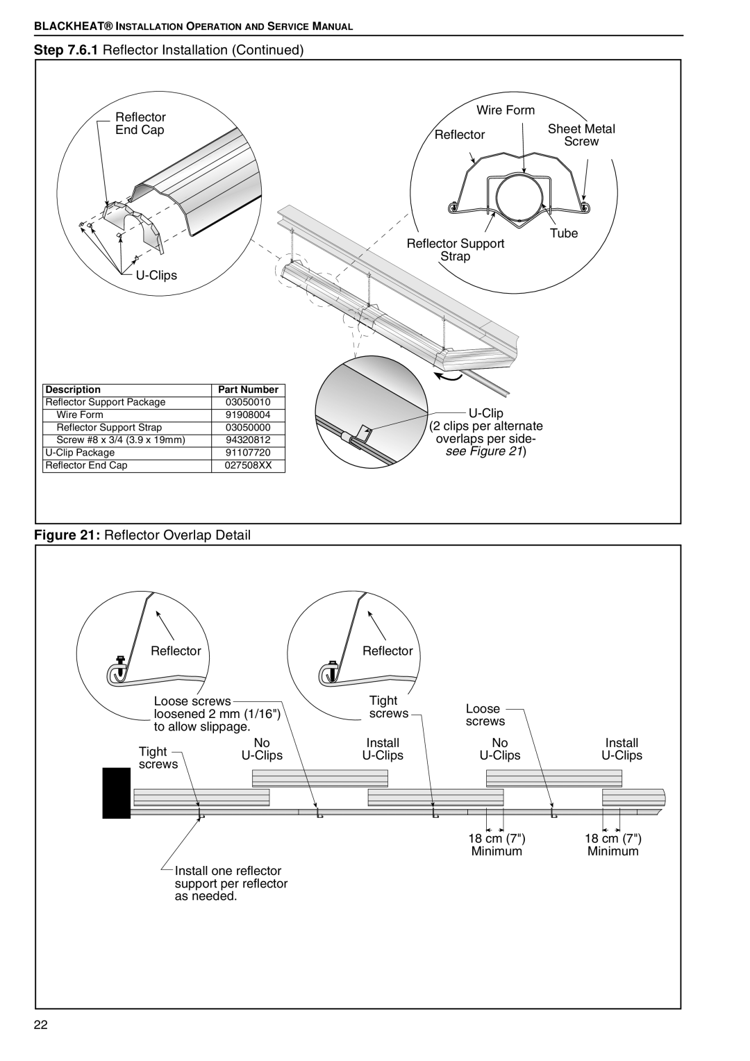
Step 7.6.1 Reflector Installation (Continued) |
|
| |
Reflector |
| Wire Form |
|
|
| Sheet Metal | |
End |
| Reflector | |
|
| Screw | |
|
|
| |
|
| Reflector Support | Tube |
|
|
| |
|
| Strap |
|
|
|
| |
Description | Part Number |
|
|
Reflector Support Package | 03050010 |
| |
Wire Form | 91908004 |
| |
Reflector Support Strap | 03050000 | (2 clips per alternate |
|
Screw #8 x 3/4 (3.9 x 19mm) | 94320812 | overlaps per side- |
|
91107720 | see Figure 21) |
| |
Reflector End Cap | 027508XX |
|
|
Figure 21: Reflector Overlap Detail
Reflector |
Reflector |
Loose screws loosened 2 mm (1/16") to allow slippage.
Tight screws
| Tight | Loose |
|
| ||
| screws |
|
| |||
| screws |
|
| |||
|
|
|
| |||
Install |
| No | Install | |||
|
|
|
|
|
|
|
|
|
|
|
|
|
|
|
|
|
|
|
|
|
|
|
|
|
|
|
|
|
|
|
|
|
|
|
|
|
|
|
|
|
|
|
|
|
|
|
|
|
|
|
|
|
|
|
|
|
|
|
|
|
|
|
18 cm (7") | 18 cm (7") |
Minimum | Minimum |
Install one reflector support per reflector as needed.
22