SECTION 7: LINEAR HEATER INSTALLATION
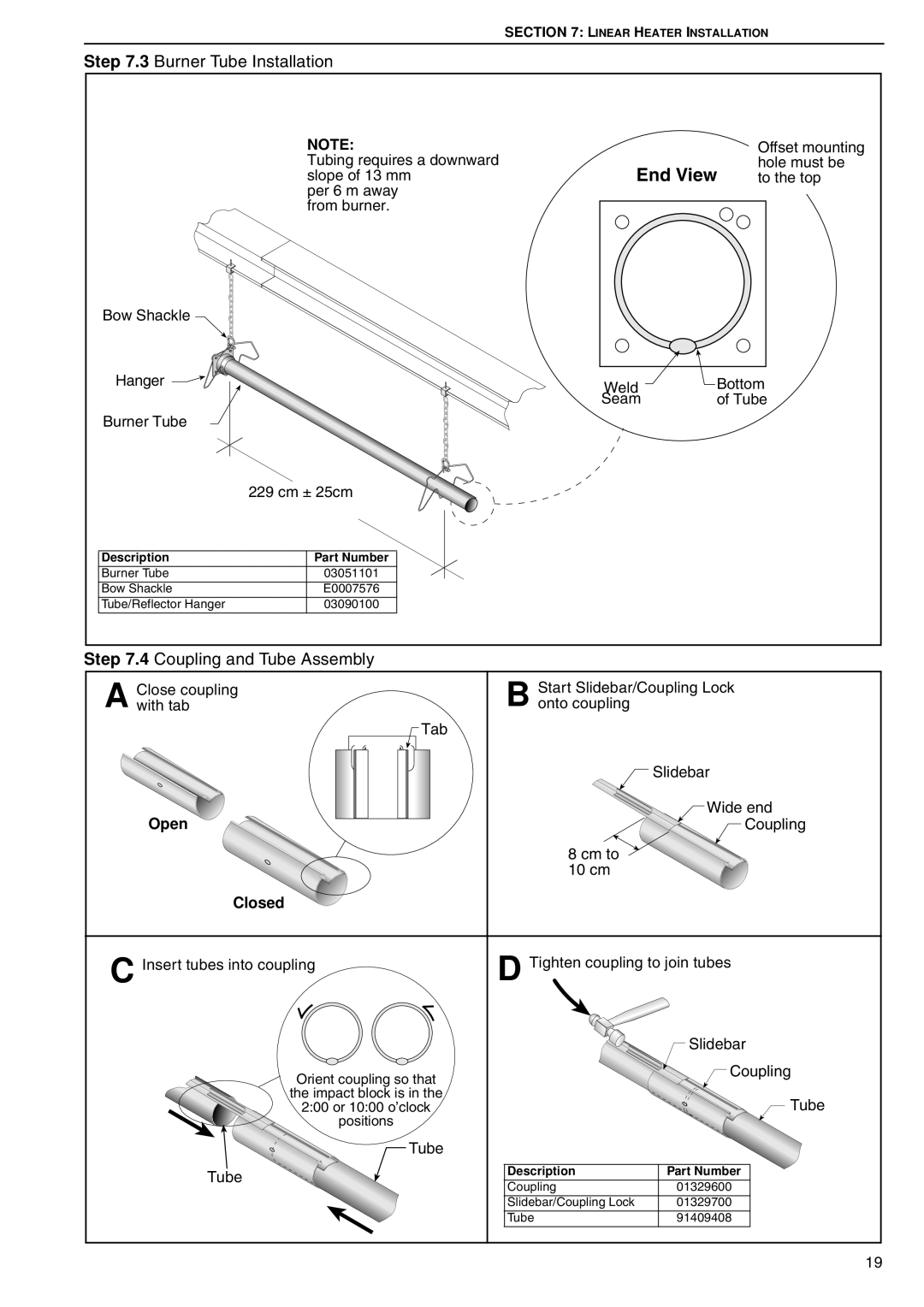
Step 7.3 Burner Tube Installation
| NOTE: |
|
| Offset mounting |
| Tubing requires a downward | End View | hole must be | |
| slope of 13 mm | to the top | ||
| per 6 m away |
|
|
|
| from burner. |
|
|
|
Bow Shackle |
|
|
|
|
Hanger |
| Weld | Bottom | |
|
| Seam | of Tube | |
Burner Tube |
|
|
|
|
| 229 cm ± 25cm |
|
|
|
Description | Part Number |
|
|
|
Burner Tube | 03051101 |
|
|
|
Bow Shackle | E0007576 |
|
|
|
Tube/Reflector Hanger | 03090100 |
|
|
|
Step 7.4 Coupling and Tube Assembly
Close coupling | Start Slidebar/Coupling Lock |
A with tab | B onto coupling |
| Tab |
| Slidebar |
| Wide end |
Open | Coupling |
| 8 cm to |
| 10 cm |
Closed |
|
C Insert tubes into coupling | D Tighten coupling to join tubes | ||
|
| Slidebar | |
Orient coupling so that |
| Coupling | |
|
| ||
the impact block is in the |
| Tube | |
2:00 or 10:00 o’clock |
| ||
positions |
|
| |
Tube |
|
| |
Tube | Description | Part Number | |
Coupling | 01329600 | ||
| |||
| Slidebar/Coupling Lock | 01329700 | |
| Tube | 91409408 | |
19