Rotor Assembly
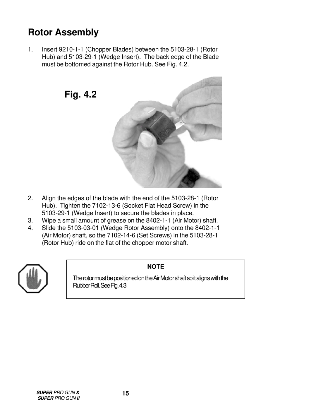
1.Insert 9210-1-1 (Chopper Blades) between the 5103-28-1 (Rotor Hub) and 5103-29-1 (Wedge Insert). The back edge of the Blade must be bottomed against the Rotor Hub. See Fig. 4.2.
Fig. 4.2
2.Align the edges of the blade with the end of the 5103-28-1 (Rotor Hub). Tighten the 7102-13-6 (Socket Flat Head Screw) in the 5103-29-1 (Wedge Insert) to secure the blades in place.
3.Wipe a small amount of grease on the 8402-1-1 (Air Motor) shaft.
4.Slide the 5103-03-01 (Wedge Rotor Assembly) onto the 8402-1-1 (Air Motor) shaft, so the 7102-14-6 (Set Screws) in the 5103-28-1 (Rotor Hub) ride on the flat of the chopper motor shaft.
NOTE
TherotormustbepositionedontheAirMotorshaftsoitalignswiththe
RubberRoll.SeeFig.4.3
SUPER PRO GUN & | 15 |
SUPER PRO GUN II | |