3. Installation
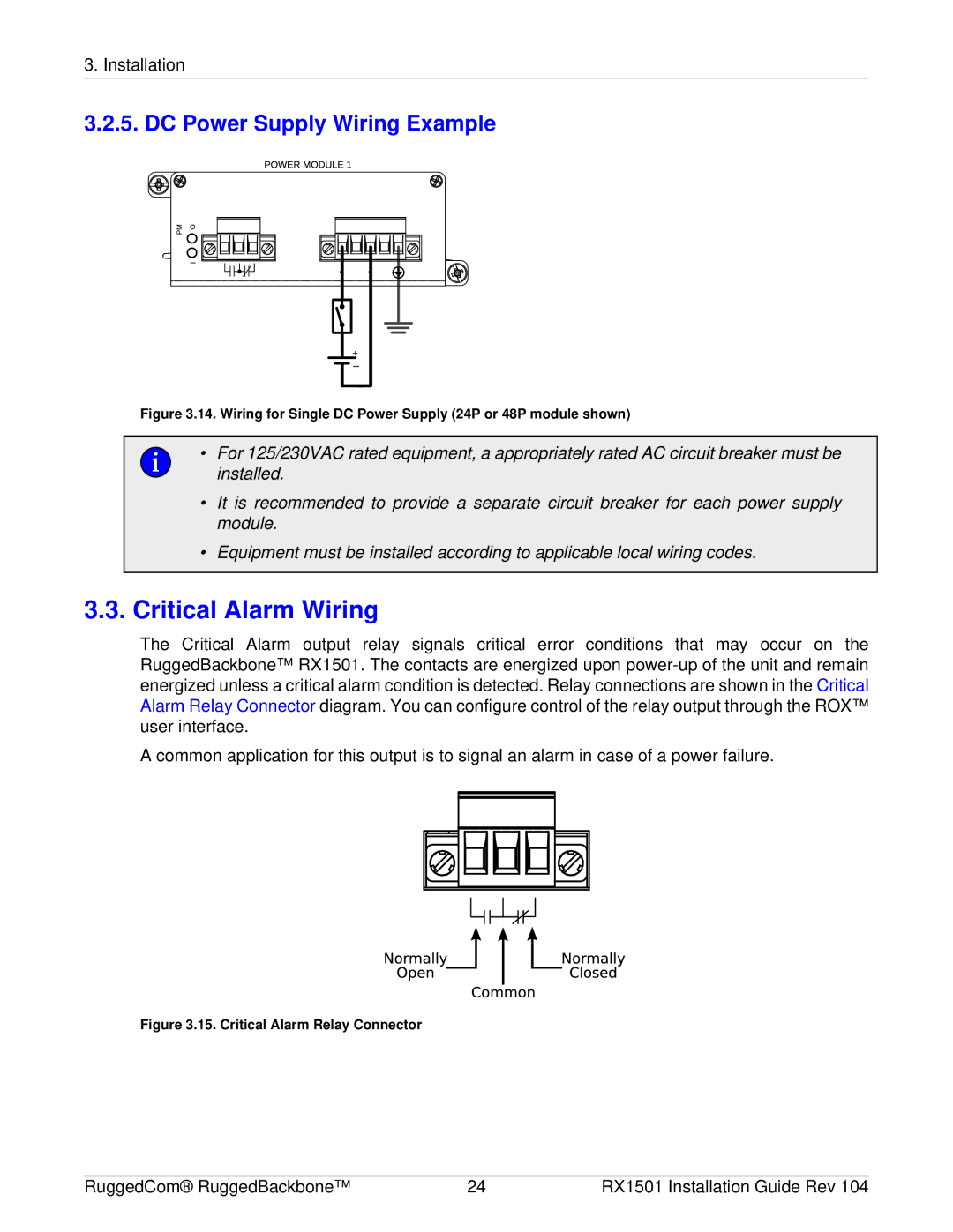
3.2.5. DC Power Supply Wiring Example
+
Figure 3.14. Wiring for Single DC Power Supply (24P or 48P module shown)
•For 125/230VAC rated equipment, a appropriately rated AC circuit breaker must be installed.
•It is recommended to provide a separate circuit breaker for each power supply module.
•Equipment must be installed according to applicable local wiring codes.
3.3.Critical Alarm Wiring
The Critical Alarm output relay signals critical error conditions that may occur on the RuggedBackbone™ RX1501. The contacts are energized upon
A common application for this output is to signal an alarm in case of a power failure.
Figure 3.15. Critical Alarm Relay Connector
RuggedCom® RuggedBackbone™ | 24 | RX1501 Installation Guide Rev 104 |