4. Technical Specifications
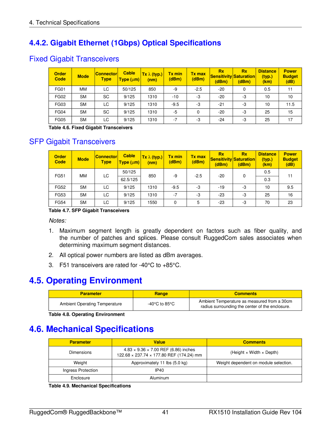
4.4.2. Gigabit Ethernet (1Gbps) Optical Specifications
Fixed Gigabit Transceivers
Order |
| Connector | Cable | Tx λ (typ.) | Tx min | Tx max | Rx | Rx | Distance | Power | |
Mode | Sensitivity | Saturation | (typ.) | Budget | |||||||
Code | Type | Type (μm) | (nm) | (dBm) | (dBm) | ||||||
| (dBm) | (dBm) | (km) | (dB) | |||||||
|
|
|
|
|
|
| |||||
FG01 | MM | LC | 50/125 | 850 | 0 | 0.5 | 11 | ||||
|
|
|
|
|
|
|
|
|
|
| |
FG02 | SM | SC | 9/125 | 1310 | 10 | 10 | |||||
|
|
|
|
|
|
|
|
|
|
| |
FG03 | SM | LC | 9/125 | 1310 | 10 | 11.5 | |||||
|
|
|
|
|
|
|
|
|
|
| |
FG04 | SM | SC | 9/125 | 1310 | 0 | 25 | 15 | ||||
|
|
|
|
|
|
|
|
|
|
| |
FG05 | SM | LC | 9/125 | 1310 | 25 | 17 | |||||
|
|
|
|
|
|
|
|
|
|
|
Table 4.6. Fixed Gigabit Transceivers
SFP Gigabit Transceivers
Order |
| Connector | Cable | Tx λ (typ.) | Tx min | Tx max | Rx | Rx | Distance | Power | |
Mode | Sensitivity | Saturation | (typ.) | Budget | |||||||
Code | Type | Type (μm) | (nm) | (dBm) | (dBm) | ||||||
| (dBm) | (dBm) | (km) | (dB) | |||||||
|
|
|
|
|
|
| |||||
FG51 | MM | LC | 50/125 | 850 | 0 | 0.5 | 11 | ||||
|
| ||||||||||
62.5/125 | 0.3 | ||||||||||
|
|
|
|
|
|
|
|
| |||
|
|
|
|
|
|
|
|
|
|
| |
FG52 | SM | LC | 9/125 | 1310 | 10 | 9.5 | |||||
|
|
|
|
|
|
|
|
|
|
| |
FG53 | SM | LC | 9/125 | 1310 | 25 | 16 | |||||
|
|
|
|
|
|
|
|
|
|
| |
FG54 | SM | LC | 9/125 | 1550 | 0 | 5 | 70 | 23 | |||
|
|
|
|
|
|
|
|
|
|
|
Table 4.7. SFP Gigabit Transceivers
Notes:
1.Maximum segment length is greatly dependent on factors such as fiber quality, and the number of patches and splices. Please consult RuggedCom sales associates when determining maximum segment distances.
2.All optical power numbers are listed as dBm averages.
3.F51 transceivers are rated for
4.5.Operating Environment
Parameter | Range | Comments | |
Ambient Operating Temperature | Ambient Temperature as measured from a 30cm | ||
radius surrounding the center of the enclosure. | |||
|
| ||
|
|
| |
Table 4.8. Operating Environment |
|
|
4.6. Mechanical Specifications
Parameter | Value | Comments | |
Dimensions | 4.83 × 9.36 × 7.00 REF (6.86) inches | (Height × Width × Depth) | |
122.68 × 237.74 × 177.80 REF (174.24) mm | |||
|
| ||
|
|
| |
Weight | Approximately 11 lbs (5.0 kg) | Weight dependent on module selection. | |
|
|
| |
Ingress Protection | IP40 |
| |
|
|
| |
Enclosure | Aluminum |
| |
|
|
|
Table 4.9. Mechanical Specifications
RuggedCom® RuggedBackbone™ | 41 | RX1510 Installation Guide Rev 104 |