Manuals
/
RuggedCom
/
Computer Equipment
/
Network Router
RuggedCom
manual
RX1510Dimensions Top View
Models:
RX1510
1
19
45
45
Download
45 pages
21.18 Kb
16
17
18
19
20
21
22
23
Specs
Install
FAQ
Critical Alarm Wiring
LED Indicators
AC Power Supply Wiring
Warranty
Dimension
Power Supply
DDS Digital Data Services
Page 19
Image 19
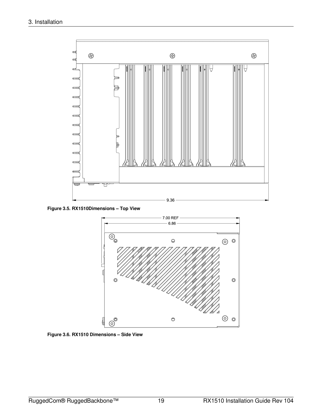
3. Installation
Figure 3.5. RX1510Dimensions – Top View
Figure 3.6. RX1510 Dimensions – Side View
RuggedCom® RuggedBackbone™
19
RX1510 Installation Guide Rev 104
Page 18
Page 20
Page 19
Image 19
Page 18
Page 20
Contents
RuggedBackbone RX1510
Registered Trademarks
Warranty Contacting RuggedCom
All Rights Reserved
Disclaimer Of Liability
Table of Contents
Page
List of Figures
Page
List of Tables
FCC Statement And Cautions
Product Overview
Feature Highlights
Functional Overview
WAN
LM1 through LM4
RuggedBackbone Modules
Orange = Warning alert
Front Panel
Module Status LEDs
Purpose Description Green = OK LM 1 through
Ethernet Copper
Line Modules LM
Ethernet Fiber
Cellular Modem
SFP Modular
WAN
Serial
APE Appplication Processing Engine
DDS Digital Data Services
27. Pluggable terminal block power module HIP module shown
Power Supply
Mounting
Installation
DIN Rail Mounting Side View
1. RX1510Dimensions
RX1510Dimensions Top View
Connectors for HI and HIP Power Modules
Power Supply Wiring and Grounding
Connectors for 24, 24P, 48, and 48P Power Modules
Chassis Ground Connection
AC Power Supply Wiring
AC and DC Power Supply Wiring Example
DC Power Supply Wiring Examples
15. Critical Alarm Relay Connector
Critical Alarm Wiring
T1/E1 pinout
RJ45 Pin Signal Function
Serial Console Port
WAN Ports RJ45
Gigabit Ethernet 1000Base-TX Cabling Recommendations
WAN Ports BNC
Copper Ethernet Ports
1. RJ45 Twisted-Pair Copper Ports
Cabling Category 1000Base Required Action
Transient Suppression
RJ45 Pin Description
Pin RS232 Mode RS485 Mode RS422 Mode
Serial Ports RJ45
DDS Ports RJ45
Tx LED Color Status
SFP Optics Installation, removal, and precautions
DDS Rx and Tx LED Indications
Rx LED Color Status
SFP Module Removal
Module Insertion SFP
25. SFP module removal
Fiber Ethernet Ports
Module Order Code Description
Cellular Modems
GSM, EDGE, HSPA+ Cellular Modem Card
Installing SIM Cards for GSM, EDGE, HSPA+ Cellular Modems
Page
Supported Operating Systems
Feature Description
APE Application Processing Engine
APE Overview
Placing the APE in a Vlan
Secondary Network Interface
Procedure 3.1. To install an operating system
Installing an Operating System
LED Color and State
APE Bios
Resetting the Module
LED Indicators
FAQs
Copper Ethernet Port Specifications
Technical Specifications
Power Supply Specifications
Critical Alarm Relay Specifications
Order
Fiber Ethernet Port Specifications
Fast Ethernet 100Mbps Optical Specifications
Cable Tx λ typ Tx min Tx max Distance Power
Gigabit Ethernet 1Gbps Optical Specifications
Mechanical Specifications
Operating Environment
Test Description Test Levels Severity
EMI And Environmental Type Tests
Test Description Test Levels
Ieee 1613 C37.90.x EMI Immunity Type Testsa
Agency Standards Comments
Agency Approvals
RuggedCom Inc
Warranty
Top
Page
Image
Contents