2. RuggedBackbone™ Modules
2.3. Power Supply
The RX1510 may be equipped with one or two power modules. The use of two power modules is recommended to provide redundancy and load balancing.
A single power module is capable of delivering a maximum of 42W, and accepts either AC or DC power at its input.
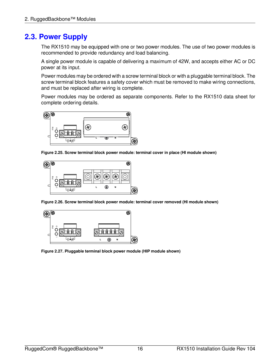
Power modules may be ordered with a screw terminal block or with a pluggable terminal block. The screw terminal block features a safety cover which must be removed to make wiring connections, and must be replaced after wiring is complete.
Power modules may be ordered as separate components. Refer to the RX1510 data sheet for complete ordering details.
P M | O |
| I |
Figure 2.25. Screw terminal block power module: terminal cover in place (HI module shown)
M | O |
P |
|
| I |
Figure 2.26. Screw terminal block power module: terminal cover removed (HI module shown)
M | O |
P |
|
| I |
Figure 2.27. Pluggable terminal block power module (HIP module shown)
RuggedCom® RuggedBackbone™ | 16 | RX1510 Installation Guide Rev 104 |