Manuals
/
Runco
/
Home Audio
/
Home Theater System
Runco
LS-3, LS-5
operation manual
Models:
LS-3
LS-5
1
25
105
105
Download
105 pages
24.46 Kb
22
23
24
25
26
27
28
29
Troubleshooting
Specs
Install
Error messages
Connecting 12-Volt
Warranty
Dimension
Connector Panel Access
Quick Setup
Key Commands
Page 25
Image 25
Page 24
Page 26
Page 25
Image 25
Page 24
Page 26
Contents
LS-3 LS-3/CineWide LS-5 LS-5/CineWide
LS-3 Series LS-5 Series
Page
RuncoCare Standard Features
RuncoCare Standard Two Year Limited Warranty
RuncoCare Claim Procedure
Page
Copyright and Trademarks
Important Safety Instructions
Declaration of Conformity
Compliance Information
FCC Part
Page
Table of Contents
Operation
Maintenance and Troubleshooting
Serial Communications
Specifications
Table of Contents Xiv
List of Figures
List of Figures Xvi
About This Manual
Introduction
If you need Turn to
Using This Manual
Description, Features and Benefits
Additional Features of the LS-5
LS-3/LS-5 at a Glance
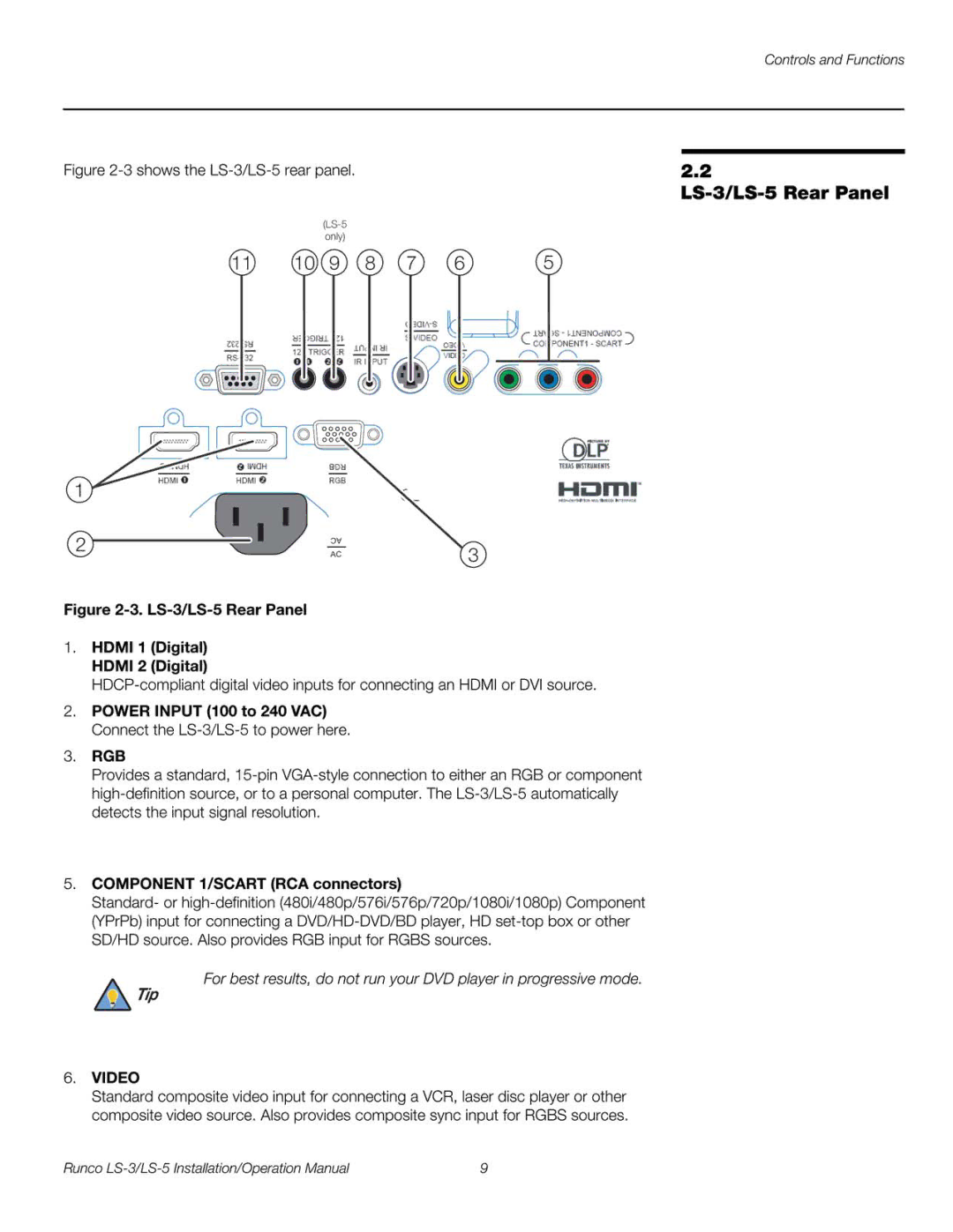
Controls and Functions
Source
LS-3/LS-5 Rear/Bottom/Top View
Runco Logo Badge
Page
Page
Projector on
LS-3/LS-5 Remote Control
PIP
Remote Control
Installation
Operation
IR Reception Angles
Installation Overview
Quick Setup
Step Procedure
For Details, Refer
Projector Installation Options
Installation
Installation Type
Considerations
Throw Distance
Ambient Light
Vertical and Horizontal
Throw Ratios for the LS-3/LS-5 Series
Position
Lens Shift
Horizontal Lens Shift Example Only
Folded Optics
Installing the Optional CineWide Lens Mount
Other Considerations
CineWide Base Plate
Installing the Fixed
Do not use the mounting screws provided with the ceiling
Mounting the LS-3/LS-5
Connections to
Connector Panel Access
LS-3/LS-5
HDMI/DVI Connections See Figure
Connecting Source Components to the LS-3/LS-5
RGB Connections
Page
11. Composite and S-Video Connections
Connection
RS-232 Controller
Connecting an External IR
Connecting 12-Volt
Trigger Output to External
Theater Equipment
Connecting to AC Power
Turning on the Power Lens Adjustments
Focus and Zoom Lens Shift
Zoom Out Focus Zoom
Installation
Rear Projection Ceiling Mode
Changing the OSD Language Adjusting the Picture Orientation
It is extremely important that the primary lens is properly
Installing and Adjusting the CineWide Anamorphic Lens
Adjusting the Lens Height and Angle
Correct Lens Angle Incorrect Lens Angle
Selecting Video Memory
Operation
Selecting an Aspect Ratio
Selecting An Input Source
Available Main and PIP Source Combinations
Using Picture-In-Picture PIP
PIP Input Source
Main
Using the On-Screen Menus
LS-3/LS-5 OSD Menu Structure
LS-3/LS-5 Main Menu
Main
169
Aspect Ratio Settings
Narrow
169
Native
You must enter a passcode to access the Save ISF
Typical Pluge Pattern for Adjusting Brightness
Typical Test Pattern for Adjusting Sharpness
Operation
Overscan Examples
Source Select Sub-Menu
LS-3/LS-5 Advanced Menu
Advanced
Operation
Color
X/y Color Gamut Values
RGB Adjust Sub-Menu
10. Fine Sync Sub-Menu
Operation
11. LS-3/LS-5 System Menu
System
12. Source Enable Sub-Menu
PBP1 PBP2
14. PIP Split-Screen Mode
Control
Page
Language
15. LS-3/LS-5 Service Menu
OSD menus are not available when in test pattern mode
Operation
Lamp Replacement
Maintenance and Troubleshooting
Troubleshooting Chart
Troubleshooting Tips
Symptom Possible Causes Solution
Troubleshooting Chart
Maintenance and Troubleshooting
Serial Communications
Key Commands
RS232 Remote Button IR Code Description Keyname Set
Serial Command Key Names and IR Codes
Gam.crt
Lit.tog
Operations Control Commands Function Action on unit
Operation Commands Values
Serial Commands
Save.mem
Source.sel = ?
Satco = ?
Auto.pow.off = ?
Act.source
Status
Error Code LED Indication Description
RS-232 Error Codes
Page
LS-3/LS-5 Specifications
Weight without lens
Dimensions
Operating Temperature
Universal Power Supply
1shows the LS-3/LS-5 dimensions, in millimeters
LS-3/LS-5 Dimensions
Supported Timings
Supported Signal Timings by Input
PAL-B/G
Top
Page
Image
Contents