OPERATION
TO ADJUST THE BLADE DEPTH
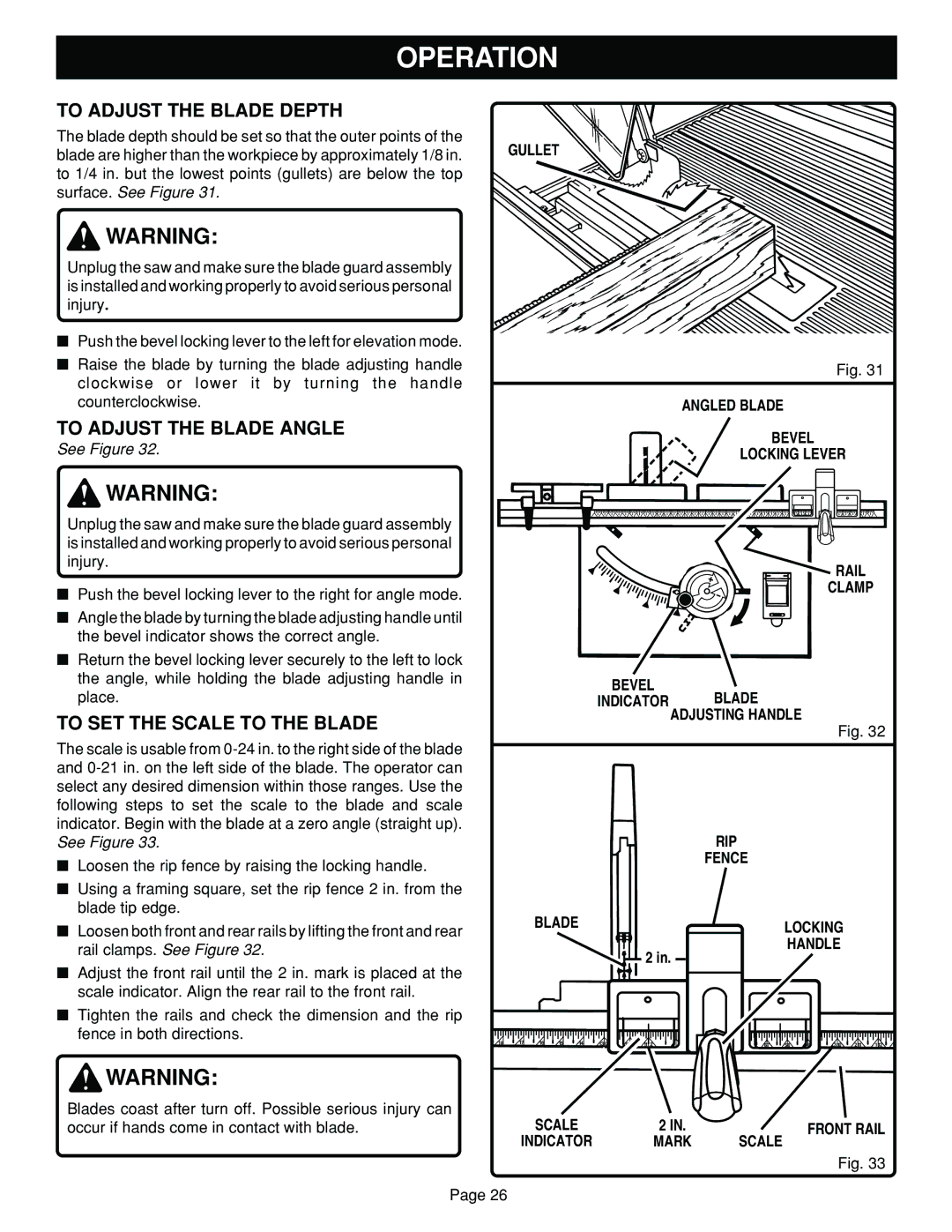
The blade depth should be set so that the outer points of the
blade are higher than the workpiece by approximately 1/8 in. GULLET to 1/4 in. but the lowest points (gullets) are below the top
surface. See Figure 31.
![]() WARNING:
WARNING:
Unplug the saw and make sure the blade guard assembly is installed and working properly to avoid serious personal injury.
■Push the bevel locking lever to the left for elevation mode.
■Raise the blade by turning the blade adjusting handle clockwise or lower it by turning the handle counterclockwise.
TO ADJUST THE BLADE ANGLE
See Figure 32.
Fig. 31
ANGLED BLADE
BEVEL
LOCKING LEVER
![]() WARNING:
WARNING:
Unplug the saw and make sure the blade guard assembly is installed and working properly to avoid serious personal injury.
■Push the bevel locking lever to the right for angle mode.
■Angle the blade by turning the blade adjusting handle until the bevel indicator shows the correct angle.
■Return the bevel locking lever securely to the left to lock the angle, while holding the blade adjusting handle in place.
TO SET THE SCALE TO THE BLADE
The scale is usable from
■Loosen the rip fence by raising the locking handle.
■Using a framing square, set the rip fence 2 in. from the blade tip edge.
■Loosen both front and rear rails by lifting the front and rear rail clamps. See Figure 32.
■Adjust the front rail until the 2 in. mark is placed at the scale indicator. Align the rear rail to the front rail.
■Tighten the rails and check the dimension and the rip fence in both directions.
![]() RAIL
RAIL
CLAMP
BEVEL
INDICATOR BLADE
ADJUSTING HANDLE
Fig. 32
|
|
|
|
|
|
|
| RIP |
|
|
|
|
|
|
|
|
|
|
|
|
|
| FENCE |
|
|
|
|
|
|
|
| BLADE |
|
|
|
|
| LOCKING |
|
|
| |||
|
|
|
|
|
|
| 2 in. |
| HANDLE |
|
|
| ||
|
|
|
|
|
|
|
|
|
|
|
|
|
| |
18 | 17 | 16 | 15 | 14 | 13 0 | 12 1 | 11 2 | 6 7 | 5 8 | 6 9 | 3 10 | 2 11 | 1 12 | 0 |
![]() WARNING:
WARNING:
Blades coast after turn off. Possible serious injury can occur if hands come in contact with blade.
Page 26
SCALE | 2 IN. | FRONT RAIL |
INDICATOR | MARK | SCALE |
|
| Fig. 33 |