MAINTENANCE
■ Make two or three test cuts on scrap wood. If the cuts are | BLADE | |
not true, repeat the process. | ||
ADJUSTING HANDLE | ||
|
WARNING:
Before plugging the saw back in to make test cuts, make sure the switch is in the OFF position and the blade guard is in place. Failure to do so may result in serious injury.
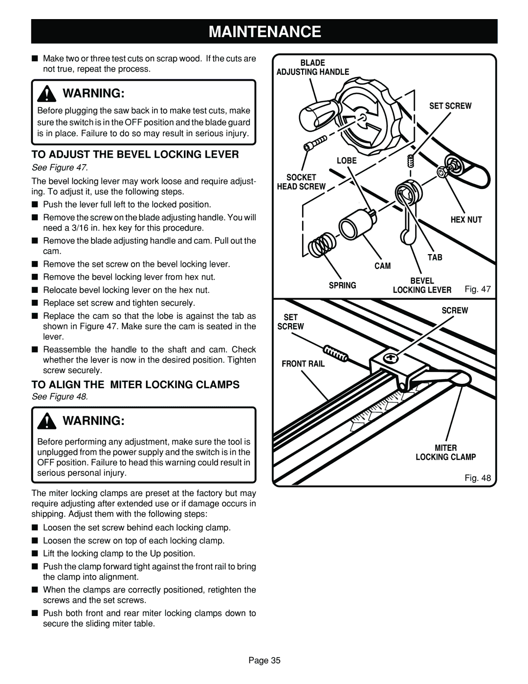
TO ADJUST THE BEVEL LOCKING LEVER
See Figure 47.
The bevel locking lever may work loose and require adjust- ing. To adjust it, use the following steps.
■Push the lever full left to the locked position.
■Remove the screw on the blade adjusting handle. You will need a 3/16 in. hex key for this procedure.
■Remove the blade adjusting handle and cam. Pull out the cam.
■Remove the set screw on the bevel locking lever.
■Remove the bevel locking lever from hex nut.
■Relocate bevel locking lever on the hex nut.
■Replace set screw and tighten securely.
■Replace the cam so that the lobe is against the tab as shown in Figure 47. Make sure the cam is seated in the lever.
■Reassemble the handle to the shaft and cam. Check whether the lever is now in the desired position. Tighten screw securely.
TO ALIGN THE MITER LOCKING CLAMPS
See Figure 48.
WARNING:
Before performing any adjustment, make sure the tool is unplugged from the power supply and the switch is in the OFF position. Failure to head this warning could result in serious personal injury.
The miter locking clamps are preset at the factory but may require adjusting after extended use or if damage occurs in shipping. Adjust them with the following steps:
■Loosen the set screw behind each locking clamp.
■Loosen the screw on top of each locking clamp.
■Lift the locking clamp to the Up position.
■Push the clamp forward tight against the front rail to bring the clamp into alignment.
■When the clamps are correctly positioned, retighten the screws and the set screws.
■Push both front and rear miter locking clamps down to secure the sliding miter table.
SET SCREW
LOBE
SOCKET
HEAD SCREW
| HEX NUT | ||
| TAB |
| |
| CAM |
| |
SPRING | BEVEL | Fig. 47 | |
LOCKING LEVER | |||
| |||
SCREW
SET
SCREW
FRONT RAIL
MITER
LOCKING CLAMP
Fig. 48
Page 35