Series Model CLP-300 B/W 16 ppm, Color 4 ppm, SPL-C
Sheets Semi-cassette Sheet manual slot Sheet Face-Down
Version no
Contents
Information Related in Disassembly and Assembly
How to use EDC Engine Diagnostic Control Mode
Block diagram
Reference Information
Precautions
Safety Warning
Electric Shock and Fire Safety Precautions
Toxic material
Handling Precautions
Assembly / Disassembly Precautions
Ensure the printer is installed safely
Be careful with the high temperature part
When you move the printer
Disregarding this warning may cause bodily injury
ESD Precautions
Super Capacitor or Lithium Battery Precautions
Product Specifications
Product Overview
Specifications
General Specifications
Controller & S/W
Paper Handling
Consumables
Environment Options Accessory
Model Comparison Table
System Structure
Main Parts of System
Fuser Ass
Cassette
LSULaser Scan Unit
ITBIntermediate Transfer Belt & 1st Transfer Roller
EP Process
Structure of EP Process
System Outline Paper path
Charging
Developing
Exposing
Transfer
Fusing
Roll system
Main PBA Description
Main Controller PBA
Main PBA
Main PBA Description
CHORUSm
Channels ADC Control Unit 2 Channels DAC Control Unit
CHORUSm Internal Block Diagram
USB2.0 Device Block
System Memory Block
Flash Memory Block
Network Block
ADC Control
Clutches Control
PWM Control
DAC Control
AC Output
SMPSSwitching Mode Power Supply PBA
DC Output
Fuser UnitHeat Lamp, Thermostat
HVPSHigh Voltage Power Supply PBA
1st Transfer High Voltage T1+
T2 Cleaning Voltage Clean T2
Charger Voltage Charger
2nd Transfer High Voltage T2+
Crum
Case of Refill Toner Install
Process after CRU life expiration
Crum Position
Processor
General Description
Controller
Printer Language Emulations
Control Panel
Periodic Replacing Parts
Interfaces
Items
Sensor
Power Switch
Operator Panel
Crums
Status Monitor
Architecture
Language Monitor
Can start polling to get the printer status
Printer Driver Status Monitor
Network Interface
System F/W Flow
LPEC2
Alarm Shortage
Error status
Crum Overview
FW Upgrade
Crum stores the following information
Initailize Flow
Samsung Electronics
Information Related in Disassembly and Assembly page5-5
Precautions When Replacing Parts page5-2
Parts for Maintenance and Repair
Disassembly Procedure page5-10
Preautions when handling PBA
Precautions when replacing parts
Precautions when assembling and disassembling
Releasing Plastic Latches
Replacement interval for parts with a limited life
Parts for Maintenance and Repair
Items Pages Printed Part number
Printer Cleaning
Information Related to Disassembly and Assembly
Special service parts
Screws used in the printer
Samsung Electronics
Disassembly and Reassembly
Samsung Electronics
Cover Unit
Disassembly Procedure
Top Cover
Fuser Ass’y
Remove the Left Cover
HVPSHigh Voltage Power Supply
LSULaser Scan Unit
SMPSSwitching Mode Power Supply
Main Board
Transfer Roller
Follow through in Cover Unit Remove the Smps Disassembly
Drive Ass’y
Open Rear Cover
Architecture
Overview
Data and Control Flow
Function
KEY Function
LED Function
Firmware downloads mode function
Black only key input process
Toner-low Status Green/Red
Service Error LED Operation
Status LED
CMYKLEDs
Start & end
Assert Error LED Operation
Onds and then All LEDs turn OFF for approximately 3 seconds
Jam Removal
Clearing Paper Jams
Close the rear cover and then open the top cover
Cover will then close automatically
Tips for Avoiding Paper Jams
Sample Pattern
Printing a Configuration
Printing a Demo
Alignment and Adjustmens
Samsung Electronics
Periodic Defective Image
Keys
How to use EDC Engine Diagnostic Control Mode
Enterence
EDC Map
Motor Test
Solenoid Test
3.3 LSU/ Fuser Test
Hvps Test
Error list and recovery
Maintenance
Off Message is disappeared
Alignment and Adjustmens
Error Message
LED status legend LED pattern Possible Problem and Solution
Troubleshooting
Procedure of Checking the Symptoms
See Solving General Printing Problems
Troubleshooting Checklist
Printed correctly Print a short document from a
Solving General Printing Problems
Manual
Troubleshooting
Samsung Electronics
Solving Print Quality Problems
Vertical repetitive
Background scatter
Check for leaking toner. Clean the inside of the printer
Ensure that the paper is loaded properly
Character Voids
Horizontal stripes
Common Windows Problems
Common Macintosh Problems
Common Linux Problems
Am trying to print a document
Enabled even though I dont
Errors Accessible to the user owning the spooler daemon
Landscape mode, but it prints
Interactively and see if you get error messages
Dor to inform them of the issue
Major Problems Trouble shooting
Vertical Line and Band Vertical White Line
Light Image Dark Image or black
Background 6 JAM
Troubleshooting
Paper Empty Cover Open Defective motor operation
No Power Vertical Line Getting Curved LSU Error
Exploded Views and Parts List
Main
Top Cover
Rear Cover
Front Cover
Main Driver1
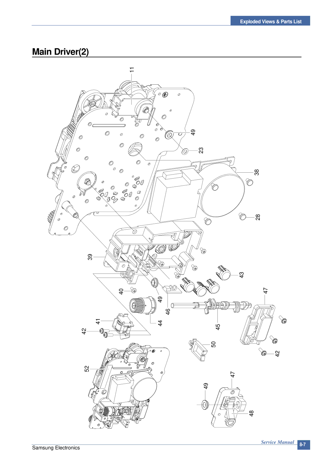
Main Driver2
Main Frame1
Main Frame2
LSU Cover
Fuser Unit
ELA-UNIT OPC DEV
ITB Unit
2114
Casstte Unit
Service Parts List Model code CLP-300/XSG
BRACKET-P-DRIVE MOTORCLP-300,SECC,T1.2 SNA
Cable CLAMPDAMC-101,D7~8,L19,SCP-1,NTR SNA
SCREW-SPECIALPH,+,-,M3,L10.3,ZPCBLK,S SNA
CBF HARNESS-FUSELINK1CLP-300,WIRE Harn
BUSH-M-TR ITBCLP-300,POMAT-15CF,ID6 SNA
SOCKET-IC8P,DIP,SN,2.54MM SNA
RUBBER-BELT BLACKCLP-300,NBR,0.7T,-,22 SNA
TONER-YELLOWCLP-300,SAY-79GZ-K1,YELLOW SNA
RING-ETCID2.2,OD6.4,T3,BLK,STS304 SNA
FRAME-M-DEVE YELLOWCLP-300,ABS+GF20%,GR SNA
SEAL-WASTE BCLP-300,POLY-URETHANESHL SNA
TANK-M-WASTECLP-300,ABSTR557A,T2.0,W1 SNA
GUIDE-M-BUSH IDL ITB LCLP-300,POM M90-4 SNA
Smps
Main
Schematic Diagrams
Main Board1/15
Main Board2/15
ADDR123 DATA031
Main Board3/15
MMSD914T1
Main Board4/15
Vclk
Main Board5/15
CLX-3160FN
Main Board6/15
1105-001384
Main Board7/15
CLX-3160NFN Only
Main Board8/15
CLP-300N & CLX-3160NFN Only
Invpower
Main Board9/15
Main Board10/15
For Debug
Main Board11/15
CLX-3160FN Only
Main Board12/15
Main Board13/15
Devehome
Main Board14/15
Bldc Itbclutch
Main Board15/15
Hvps
Panel
Deve INF
ITB INF
SMPS-110V
CON1 TNR01
SMPS-220V
Hvps 1/5
Hvps 2/5
Hvps 3/5
Hvps 4/5
Hvps 5/5
Tools for Troubleshooting
Acronyms and Abbreviations
Printer Command Language
Nonvolatile Random Access
Printed Board Assembly
A60, B60 Pins
Select a location for the printer
12.4 A4 ISO 19752 Standard Pattern
This test page is reproduced at 70% of the normal A4 size