Refrigerator
Important Safety Notice
Contents
Disassembly of Refrigerator Door Right
PCB Diagram
Connector Layout with Part Position Main Board
Connector Layout with Part Position Inverter Board
Precautionssafety Warnings
Symbols
Prohibition
Flooring
Product Specifications
Twin Cooling System
Pizza Corner
Ice and Water Dispenser
Secure Auto Close Door System
Refrigerator
Run Time,%
Dryer
Dryer Fan
Interior Views RF267
Interior Views RF26X
Model Specification &Specification Chart
C.R
Freol
Split FIN Type
OFF
Refice Room
FRE
Bsbn Brass Screw
6Dimensions of Refrigerator
11/161059mm 19/3215mm 701778mm
Optional Material Specification
DA99-00240S
4713-001223
Amount
Refrigerant Route in Refrigeration cycle
Hot Pipe Dryer Capillary Tube
Refrigerator
Evaporator
Cooling Air Circulation
Disassembly and Reassembly
Assembly & Disassembly
Refrigerator Door Part Name How To Do Descriptive Picture
Refrigerator
Blue and red clips are not
On the coupling at first, but must
Lift the door straight up to remove
Part Name How To Do Descriptive Picture
Refrigerator Door
Remove the Cap Door with a flat-blade- screwdriver
Door Handle Part Name How To Do Descriptive Picture
Door Handle Freezer
Refrigerator Light
Refrigerator Light Part Name How To Do Descriptive Picture
Cover-display
Part Name How To Do Descriptive Picture Cover-display
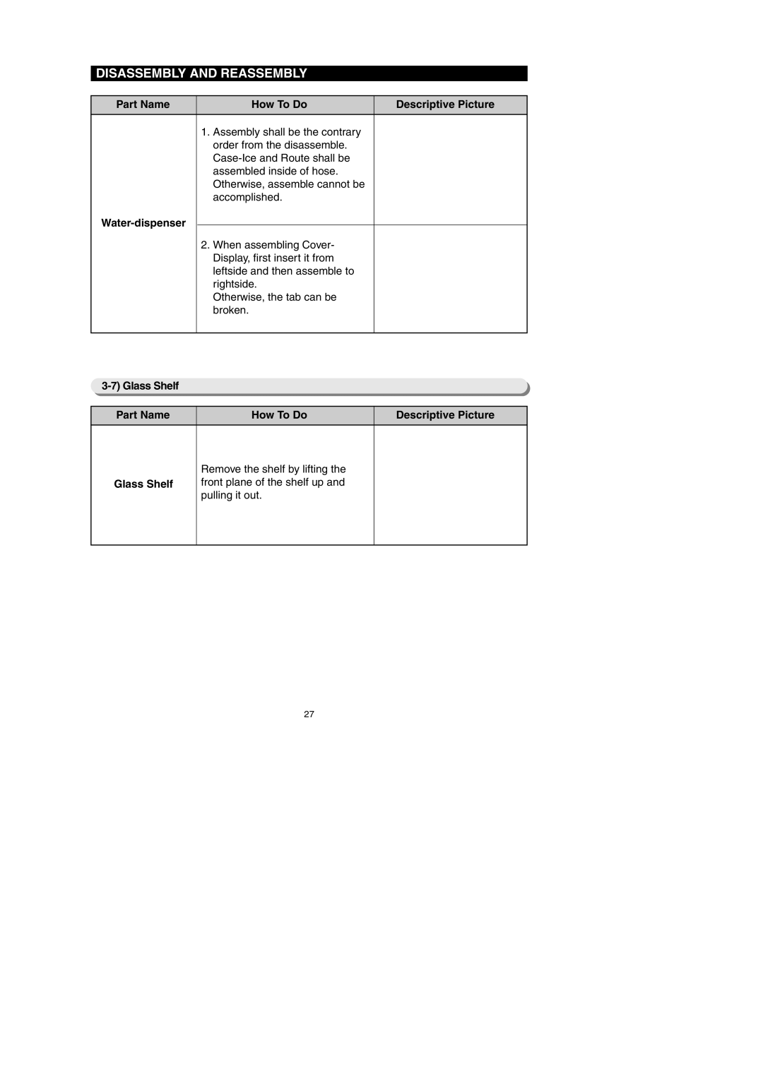
Water-dispenser Part Name How To Do Descriptive Picture
Remove 4 screws of cover- display
Water-dispenser
Glass Shelf Part Name How To Do Descriptive Picture
Remove the shelf by lifting
Glass Shelf
Front plane of the shelf up
Remove 2 screws of the Fold Glass Shelf
Vegetable & Fruit Drawers Shelf
Shelf
Cool Select Pantry Rail
Water Tank Part Name How To Do Descriptive Picture
Disengage the housing
Connector
Water Tank
Part Name How To Do Descriptive Picture Water Tank
Motor Damper
Motor Damper Part Name How To Do Descriptive Picture
Water Filter
Gallon Door Bin Part Name How To Do Descriptive Picture
Remove the gallon door bin by
Gallon Door Bin
Lifting it up
Vertical Hinged Section
Angle mid by pulling it out
Pushing it down
Evaporator Refrigerator
Freezer Door Part Name How To Do Descriptive Picture
Freezer Door
Slide the drawer in as much as possible
Pull Out Drawer Part Name How To Do Descriptive Picture
Door Handle Lift the drawer up
Lever
Ice-Maker Part Name How To Do Descriptive Picture
Ice Maker
Door Switch Freezer
Freezer Light Part Name How To Do Descriptive Picture
Freezer Light
Lift up the evaporator cover
Evaporator Freezer
Machine Compartment Part Name How To Do Descriptive Picture
Motor Fan
Remove the spring with a flat
Blade screwdriver
Relay O/L
Unscrew 2 earth screws
Unscrew 2 screws Disengage the housing connector
Noise Filter
Electric Box Part Name How To Do Descriptive Picture
PBA Main
Troubleshooting
Test mode manual operation / manual defrost function
Function for failure diagnosis
Compartment
Manual defrost of fresh food
Troubleshooting
Return to normal display mode
Self-diagnostic function during normal operation
Self-diagnosis Check List
Trouble contents
Trouble item
Self-diagnostics check list
LED
Load mode Check list
Display function of Load condition
Cooling off mode setting function
KEY control method after converting to option mode
Code Down
Refrigerator control function and is not needed at Service
Standard temperature to 4 2C
Temperature changing table of fresh food compartment
Ex If you want to change the freezer compartment
Diagnostic method according to the trouble symptomFlow Chart
Resistance
Error Code
If the trouble is detected by self-diagnosis
If ICE Maker Sensor has trouble
Start
Replace the temperature sensor
If R Sensor has trouble
Is the input voltage of IC01
If R DEF Sensor has trouble
Marking #5R313 due to the SMD Micom
#7R307 due to the SMD Micom
If Ambient Sensor has trouble
IC01 Micom #72 normal?
If F Sensor has trouble
IC01 Micom #81 normal?
#2R310 due to the SMD Micom
If F DEF Sensor has trouble
IC01 Micom #77 normal?
If Ice Room Sensor has trouble
Value Open trouble Short trouble
Typical Ground part are similar
IC01 Micom #71 normal?
Micom Pin #73 normal?
If Pantry Sensor has trouble
Checking method of Pantry Sensor voltage
If Pantry Room Damper Heater has trouble
Recheck the wire Replace PCB Main
Normalrecheck Replace Damper
Bad contact of connector
Insert correctly Wire connector Replace Heater
Normalrecheck Recheck the wire Replace PCB Main
If Tank Water Heater has trouble
If FAN does not operateF, R, C FAN
Ice Room control temperature
If ICE Room Fan does not operate
Yes
Does DC7~12V alternate
Test Mode operation will be 30 sec
2Test Switch ready
If Ice Maker does not operate
#37
DEF Error
If defrost does not operate F,R DEF Heater
If Power is not supplied
If compressor does not operate
Check after 7minutes
Replace Micom Replace PCB Replace IC72 Driver ICTD62083AP
Replace Comp Assy
Is water penetrated into the door switch?
If ding-dongsound continuously
If beep-beep sounds continuously
Is manual operation Defrost selected?
Is the damage Or breakage of the buzzer Panel PCB?
Replacerepair buzzer Replace Panel PCB Replace buzzer
Reinsert connector, Repair bad contact
Is Upper Hinge Panel PCB connector Inserted correctly?
Is lighting operate Normally when replace Panel-PCB?
If Panel PCB does not work normally
Display On 0.7V
If Pantry Panel PCB is not working normally
Convertible compartment Panel PCB itself has trouble
When refrigerator Room Lamp does not light up
If ICE Water is not supplied
= For checking the Relay RY78 operating
Typical PCB Ground CN1#3Black
If Water is not supplied
Check the connection hose
If Cubed or Crushed Ice is not supplied
If Cover Ice Route MoorGeard Motor is not working normally
Open/Close
Exploded VIEW& Parts List
Freezer
Parts List of Freezer
Switch DOOR-F
SCREW-TAPPING TH,+,1,M4,L12,ZPCWHT,SWRCH18A
REINF-DRAWER BOX AW-PJT,SHP1,T2.0,BLACK
TRAY-DRAWER BOX AW-PJT,PP,COOL White
Refrigerator
Parts List of Refrigerator
SWITCH-MICRO
COVER-VEG REF AW-SEM,HIPS,COOL White
KNOB-HUMIDITY QUEEN,ABS
LEVER-HUMIDITY AW-SEM,TALC PP,COOL White
ASSY-ROLLER a
Assy CASE-PANTRY AW-SEM
CASE-PANTRY AW-SEM,HIPS,COOL White
ASSY-ROLLER B
Cabinet
Parts List of Cabinet
AW-SEM,SNOW White
Assy Hinge UPP-R
HINGE-UPP R
GROMMET-LEVER NBR,BLACK
CBF-POWER Cord
Assy FAN-CIRCUIT AW-SEM
FAN-TURBO AW-SEM,ABS+GLASSFIBER
Grommet Comp USP05,EPDM,OD18.5,BLACK
Disassembly of Freeze Door
Parts List of Freezer Door
SLIDER-HANDLE FRE
SLIDER-HANDLE FRE AW-SEM,POM,I-BLACKSC-00477R
SLIDER-HANDLE FRE AW-SEM,POM,NTR
AW-PJT,HSWR
Disassembly of Refrigerator DoorLeft
Parts List of Refrigerator Door-Left
PLATE-FRENCH AW-PJT,SECC1,ALL Black
GASKET-FRENCH AW-PJT,SILICONE,BLACK
ASSY-FRENCH AW-SEM,SNOW White
PLATE-FRENCH AW-PJT,SECC1,SNOW White
Disassembly of Refrigerator Door Right
101
Parts List of Refrigerator Door-Right
PCB Diagram
PCB Layout with part position
Connector with AC load a. Diode option setting area
104
PCB Layout with part position Inverter Board
PWM Duty
Connector Layout with part position Main Board
1. RF267AE
PCB Layout with part position Main Board
2. RF26XAE
Connector Layout with part position Inverter Board
Model RF267AE
Model RF26XAE
Whole block diagram
Model RF267AE
Model RF26XAE
Inverter Board
Model RF267AE / RF26XAE
Circuit Diagram
PN / XAA
Refrigerator Division