Network Camera
Network Camera
Overview
Important Safety Instructions
Explanation of Graphical Symbols
Class construction
Overview
Contents
Login
Connecting to the Camera
Installing ActiveX
Installing Silverlight Runtime
Recomended PC Specifications
Product Features
Recomended SD/SDHC Memory Card Specifications
WHAT’S Included
Item Name Quantity
Front Side
AT a Glance
Connector
Auto Iris Lens Installed on the lens adaptor Optional
Terminal for audio output
Rear Side
Terminal for audio input
Abnormally
On While the power is on
System, Power
SD Indicators OFF If the power is off
Seconds to reboot the system
Mounting the C lens
Mounting the Lens
Mounting the CS lens
Mount Adapter
Focusing
Connecting the Auto Iris Lens connector
INSERTING/REMOVING a SD Memory Card
Inserting a SD Memory Card
Apply .
Removing a SD Memory Card
Memory Card Components Contacts Lock Switch
What is a memory card?
Memory Card Information not Included
Selecting a memory card that’s suitable for you
Power Supply
Connecting with Other Device
Power Ethernet
Ethernet Connection
Connecting to Audio Input/Output
Speaker Microphone
Speaker Amp
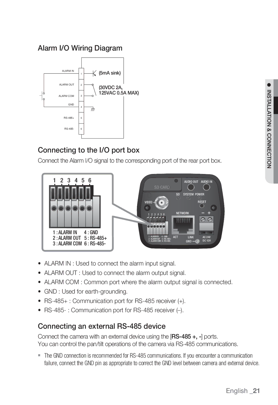
Connecting to the I/O port box
Alarm I/O Wiring Diagram
Connecting an external RS-485 device
5mA sink 30VDC 2A, 125VAC 0.5A MAX
Connecting the Camera Directly to Local Area Networking
Connecting to the camera from a local PC in the LAN
Local Network
Network Connection and Setup
Modem
Network Connection
Buttons Used in IP Installer
Manual Network Setup
Static IP Setup
Ddns registration has failed
Auto Set
Address pane, provide the necessary information
If not using a Broadband Router
If the Broadband Router has more than one camera connected
Category Camera #1 Camera #2
Http Port 8080 8081 VNP Port 4520 4521
Click OK Auto network setup will be completed
Auto Network Setup
Dynamic IP Environment Setup
Dynamic IP Setup
Manual Port Range Forwarding
Port Range Forward Port Mapping Setup
Setting up Port Range Forward for several network cameras
User Internet Broadband Router Start End
Camera1
Connecting to the Camera from a Remote PC VIA the Internet
Connecting to the Camera from a Shared Local PC
Using URL
Connecting to the Camera
Login dialog should appear
Normally, you would
To check the Ddns address
Login
Installing Activex
Installing Silverlight Runtime
English
Hide the alarm
Using the Live Screen
Monitoring Move to the monitoring screen Playback
Viewer
Control the pan/tilt/zoom operations of the camera
To capture the snapshot
Pan/tilt-compliant receiver
Optimization
To toggle the audio sound
To toggle the microphone sound
To fit the full screen
Be limited up to the date when the 500th event is recorded
Search and Play by Event
To control the PTZ
To check time information of the playing video
Search and Play by Time
To back up the searched video
To play the backup video
Setup
Audio & Video Setup
Video profile
To add a video profile
Video setup
What is GOP size?
To set the privacy zone
Audio setup
Ssdr Samsung Super Dynamic Range Setup
Camera setup
English
Setup screen
English
OSD Setup Select OSD Select each item and set it properly
External PTZ setup
Select the preset number to delete Press the button
Interface
Network Setup
Ddns
Port
Registering with Ddns
Select a Classification and specify the Model Number
IP filtering
Provide the IP that you want to grant or deny access from
802.1x
Snmp
QoS
FTP / E-mail
Event Setup
SD record
Reset all settings When done, click Apply
Alarm input
Motion detection
Object color or brightness is similar to the background
Fixed object continues moving in the same position
Time schedule
Tampering
Network disconnect
Product information
System Setup
Date & Time
Timezone Specify the local time zone based on the GMT
Manual Specify the time manually
User
Upgrade / Reboot
English
Log
Appendix
Specification
Digital Noise Reduction
User
Tampering
264, MPEG-4, Mjpeg Resolution
Items Description Ethernet RJ-45 10/100BASE-T
Max. Framerate
Language
Operating Temperature
Hungarian, Greek
Web Viewer
Unit mm inch
Product Overview
Troubleshooting
This camera unit
Check if the memory card is defective
SD Record menu
Cannot record into the SD memory
All rights reserved
Open Source Announcement
Part 1 CMU/UCD copyright notice BSD like
License
Copyright c 2007 Apple Inc All rights reserved
Copyright c 2003-2009, Sparta, Inc All rights reserved
Copyright c 2009, ScienceLogic, LLC All rights reserved
Part 9 ScienceLogic, LLC copyright notice BSD
GPL/LGPL Software License
Base Kernel, Busybox, Sysvinit, dosfstools
GLibc, Inetutils
Page
GNU General Public License is a free, copyleft
No Warranty
You can apply it to your programs, too
Terms and Conditions
Protecting Users’ Legal Rights From Anti- Circumvention Law
Conveying Verbatim Copies
Conveying Non-Source Forms
Additional Terms
Termination
Acceptance Not Required for Having Copies
Automatic Licensing of Downstream Recipients
Patents
Use with the GNU Affero General Public License
Limitation of Liability
Disclaimer of Warranty
Interpretation of Sections 15
Version 2.1, February
Above on a medium customarily used for software interchange
Modified work must itself be a software library
Page
How to Apply These Terms to Your New Libraries
This Software is Provided by the OpenSSL
OpenSSL License
Correct disposal of batteries in this product
Toll Free +1-877-213-1222 Direct +1-201-325-6920
Sales Network