APPENDIX B Connectors |
| |
▌B.1 |
|
|
|
| |
| Interface connector | Drawer |
| Connector | |
|
| |
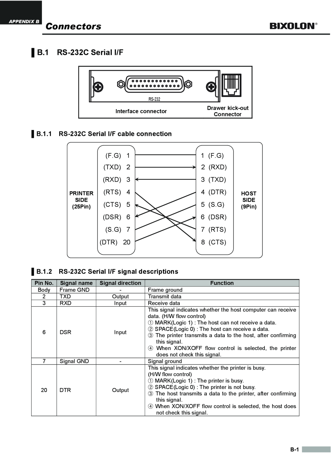
▌B.1.1 |
| |
| (F.G) | 1 |
| 1 | (F.G) |
|
|
|
| ||||
| (TXD) | 2 | 2 | (RXD) |
| |
| (RXD) | 3 | 3 | (TXD) |
| |
PRINTER | (RTS) | 4 | 4 | (DTR) | HOST | |
SIDE | (CTS) | 5 | 5 | (S.G) | SIDE | |
(25Pin) | (9Pin) | |||||
| (DSR) | 6 | 6 | (DSR) |
| |
| (S.G) | 7 | 7 | (RTS) |
| |
| (DTR) | 20 | 8 | (CTS) |
| |
▌B.1.2 RS-232C Serial I/F signal descriptions
Pin No. | Signal name | Signal direction | Function | |
Body | Frame GND | - | Frame ground | |
2 | TXD | Output | Transmit data | |
3 | RXD | Input | Receive data | |
|
|
| This signal indicates whether the host computer can receive | |
|
|
| data. (H/W flow control) | |
|
|
| ① MARK(Logic 1) : The host can not receive a data. | |
6 | DSR | Input | ② SPACE(Logic 0) : The host can receive a data. | |
③ The printer transmits a data to the host, after confirming | ||||
|
|
| ||
|
|
| this signal. | |
|
|
| ④ When XON/XOFF flow control is selected, the printer | |
|
|
| does not check this signal. | |
7 | Signal GND | - | Signal ground | |
|
|
| This signal indicates whether the printer is busy. | |
|
|
| (H/W flow control) | |
|
|
| ① MARK(Logic 1) : The printer is busy. | |
20 | DTR | Output | ② SPACE(Logic 0) : The printer is not busy. | |
③ The host transmits a data to the printer, after confirming | ||||
|
|
| ||
|
|
| this signal. | |
|
|
| ④ When XON/XOFF flow control is selected, the host does | |
|
|
| not check this signal. |
![]()