132
Connectors and Signals (Parallel Interface)
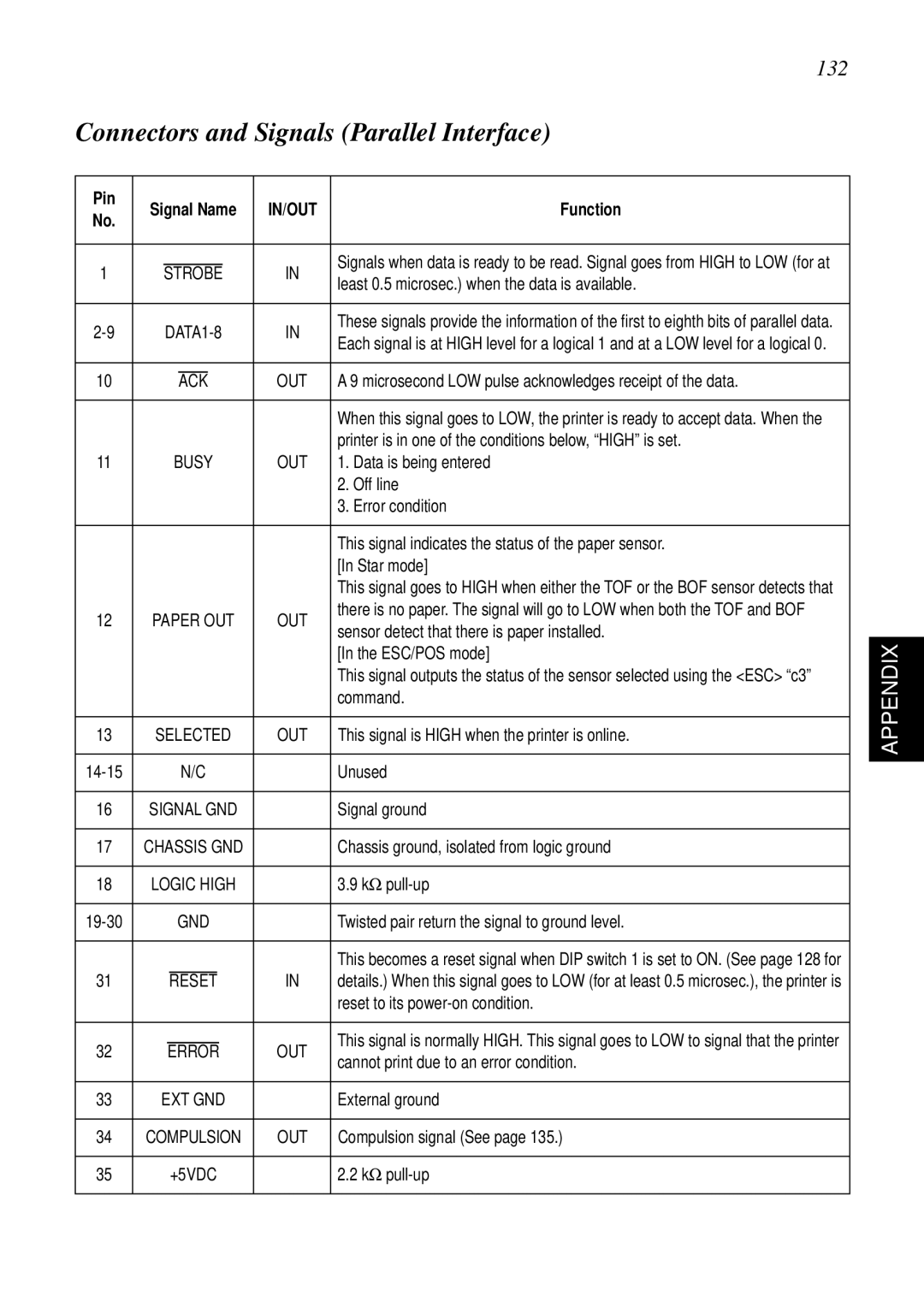
Pin | Signal Name | IN/OUT | Function |
|
| |||||||
No. |
|
| ||||||||||
|
|
|
|
|
|
|
|
|
|
|
| |
|
|
|
|
|
|
|
|
|
|
|
|
|
|
|
|
|
|
|
|
|
|
| Signals when data is ready to be read. Signal goes from HIGH to LOW (for at |
|
|
1 |
| STROBE | IN |
| ||||||||
| least 0.5 microsec.) when the data is available. |
|
| |||||||||
|
|
|
|
|
|
|
|
|
|
|
| |
|
|
|
|
|
|
|
|
|
|
|
|
|
|
| IN | These signals provide the information of the first to eighth bits of parallel data. |
|
| |||||||
| Each signal is at HIGH level for a logical 1 and at a LOW level for a logical 0. |
|
| |||||||||
|
|
|
|
|
|
|
|
|
|
|
| |
|
|
|
|
|
|
|
|
|
|
|
| |
10 |
|
|
|
|
|
|
| OUT | A 9 microsecond LOW pulse acknowledges receipt of the data. |
|
| |
|
|
| ACK |
| ||||||||
|
|
|
|
|
|
|
|
|
|
|
|
|
|
|
|
|
|
|
|
|
|
| When this signal goes to LOW, the printer is ready to accept data. When the |
|
|
|
|
|
|
|
|
|
|
|
| printer is in one of the conditions below, “HIGH” is set. |
|
|
11 |
|
| BUSY | OUT | 1. Data is being entered |
|
| |||||
|
|
|
|
|
|
|
|
|
| 2. Off line |
|
|
|
|
|
|
|
|
|
|
|
| 3. Error condition |
|
|
|
|
|
|
|
|
|
|
|
|
|
|
|
|
|
|
|
|
|
|
|
|
| This signal indicates the status of the paper sensor. |
|
|
|
|
|
|
|
|
|
|
|
| [In Star mode] |
|
|
|
|
|
|
|
|
|
|
|
| This signal goes to HIGH when either the TOF or the BOF sensor detects that |
|
|
12 | PAPER OUT | OUT | there is no paper. The signal will go to LOW when both the TOF and BOF |
|
| |||||||
sensor detect that there is paper installed. |
|
| ||||||||||
|
|
|
|
|
|
|
|
|
|
|
| |
|
|
|
|
|
|
|
|
|
| APPENDIX | ||
|
|
|
|
|
|
|
|
|
| [In the ESC/POS mode] |
| |
|
|
|
|
|
|
|
|
|
|
|
| |
|
|
|
|
|
|
|
|
|
| This signal outputs the status of the sensor selected using the <ESC> “c3” |
|
|
|
|
|
|
|
|
|
|
|
| command. |
|
|
|
|
|
|
|
| |||||||
13 | SELECTED | OUT | This signal is HIGH when the printer is online. |
|
| |||||||
|
|
|
|
|
|
|
|
|
|
|
|
|
|
|
| N/C |
| Unused |
|
| |||||
|
|
|
|
|
| |||||||
16 | SIGNAL GND |
| Signal ground |
|
| |||||||
|
|
|
|
|
| |||||||
17 | CHASSIS GND |
| Chassis ground, isolated from logic ground |
|
| |||||||
|
|
|
|
|
| |||||||
18 | LOGIC HIGH |
| 3.9 kΩ |
|
| |||||||
|
|
|
|
|
|
|
| |||||
|
| GND |
| Twisted pair return the signal to ground level. |
|
| ||||||
|
|
|
|
|
|
|
|
|
|
|
|
|
|
|
|
|
|
|
|
|
|
| This becomes a reset signal when DIP switch 1 is set to ON. (See page 128 for |
|
|
31 |
|
|
|
|
| IN | details.) When this signal goes to LOW (for at least 0.5 microsec.), the printer is |
|
| |||
|
| RESET |
| |||||||||
|
|
|
|
|
|
|
|
|
| reset to its |
|
|
|
|
|
|
|
|
|
|
|
|
|
|
|
|
|
|
|
|
|
|
|
|
| This signal is normally HIGH. This signal goes to LOW to signal that the printer |
|
|
32 |
|
| ERROR | OUT |
| |||||||
|
| cannot print due to an error condition. |
|
| ||||||||
|
|
|
|
|
|
|
|
|
|
|
| |
|
|
|
|
|
| |||||||
33 | EXT GND |
| External ground |
|
| |||||||
|
|
|
|
|
| |||||||
34 | COMPULSION | OUT | Compulsion signal (See page 135.) |
|
| |||||||
|
|
|
|
|
|
|
| |||||
35 |
|
| +5VDC |
| 2.2 kΩ |
|
| |||||
|
|
|
|
|
|
|
|
|
|
|
|
|