APPENDIX
135
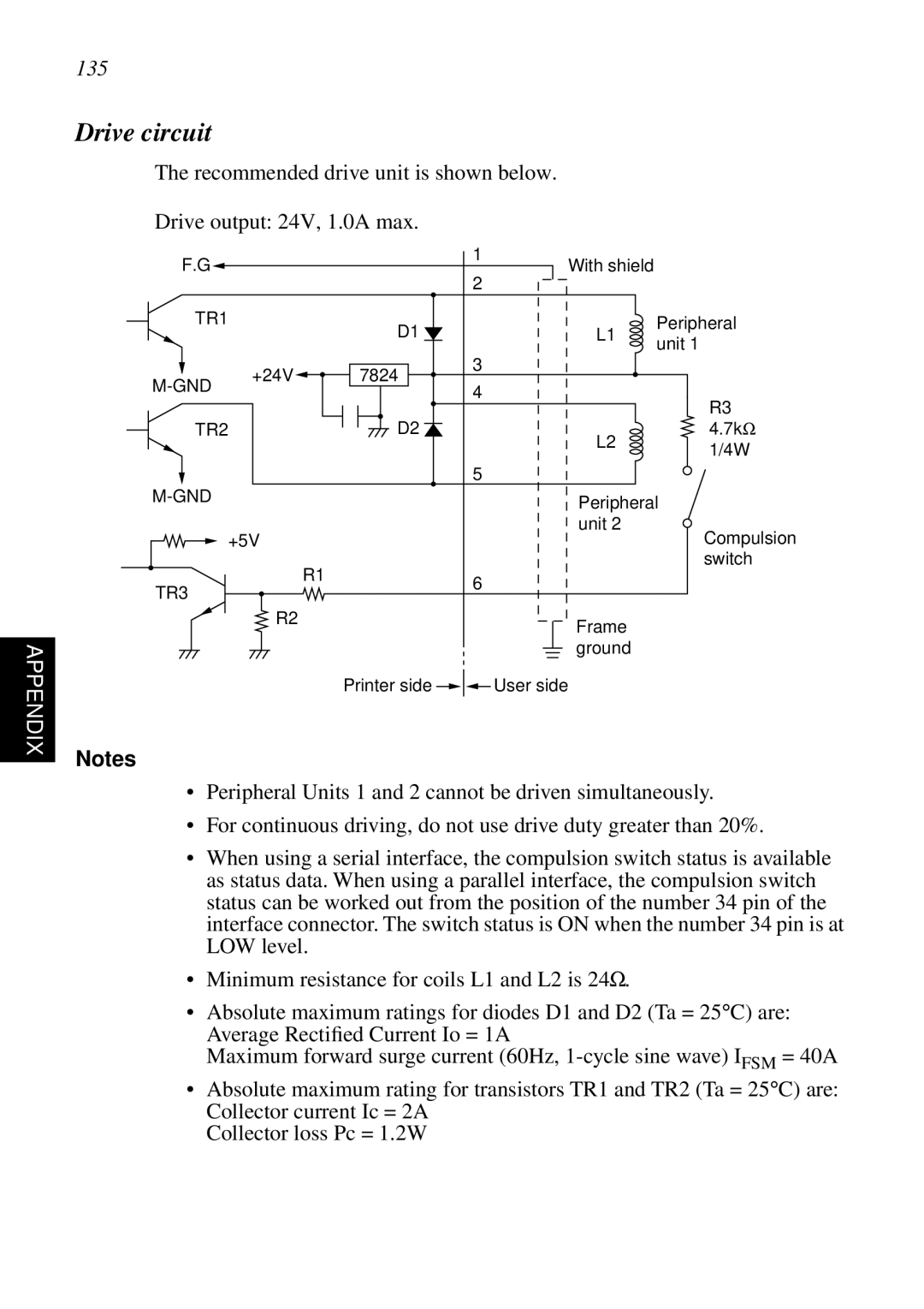
Drive circuit
The recommended drive unit is shown below.
Drive output: 24V, 1.0A max.
1
F.G![]() With shield 2
With shield 2
TR1 |
| D1 | L1 | Peripheral |
|
| unit 1 | ||
|
|
|
| |
| +24V | 7824 | 3 |
|
4 |
| |||
|
|
| ||
|
|
| R3 | |
|
|
|
| |
TR2 |
| D2 | L2 | 4.7kΩ |
|
|
| 1/4W | |
|
|
|
| |
|
|
| 5 |
|
|
| Peripheral | ||
|
|
| ||
+5V |
| unit 2 | Compulsion | |
|
| |||
|
| R1 |
| switch |
TR3 |
| 6 |
| |
|
|
| ||
|
|
|
| |
| R2 |
| Frame |
|
|
|
|
| |
|
|
| ground |
|
|
| Printer side | User side |
|
Notes
•Peripheral Units 1 and 2 cannot be driven simultaneously.
•For continuous driving, do not use drive duty greater than 20%.
•When using a serial interface, the compulsion switch status is available as status data. When using a parallel interface, the compulsion switch status can be worked out from the position of the number 34 pin of the interface connector. The switch status is ON when the number 34 pin is at LOW level.
•Minimum resistance for coils L1 and L2 is 24Ω.
•Absolute maximum ratings for diodes D1 and D2 (Ta = 25°C) are: Average Rectified Current Io = 1A
Maximum forward surge current (60Hz,
•Absolute maximum rating for transistors TR1 and TR2 (Ta = 25°C) are: Collector current Ic = 2A
Collector loss Pc = 1.2W