Part Names and Functions
Rear Terminal
qwe
r
t
o i u y
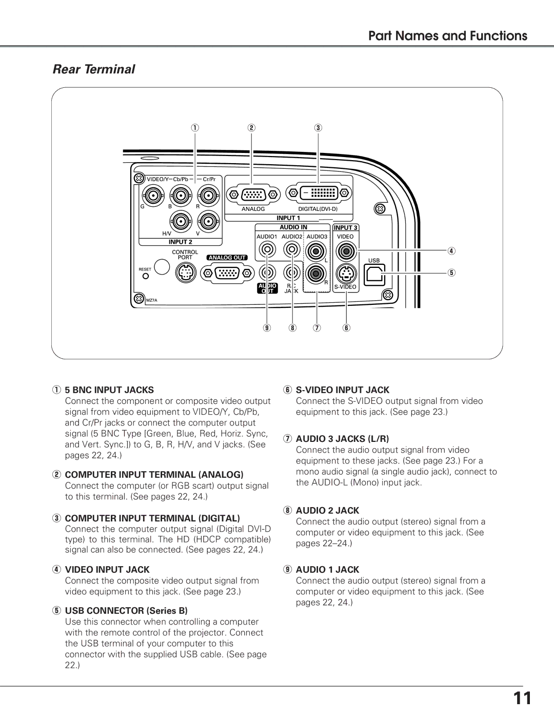
q5 BNC INPUT JACKS
Connect the component or composite video output signal from video equipment to VIDEO/Y, Cb/Pb, and Cr/Pr jacks or connect the computer output signal (5 BNC Type [Green, Blue, Red, Horiz. Sync, and Vert. Sync.]) to G, B, R, H/V, and V jacks. (See pages 22, 24.)
wCOMPUTER INPUT TERMINAL (ANALOG) Connect the computer (or RGB scart) output signal to this terminal. (See pages 22, 24.)
eCOMPUTER INPUT TERMINAL (DIGITAL) Connect the computer output signal (Digital
rVIDEO INPUT JACK
Connect the composite video output signal from video equipment to this jack. (See page 23.)
tUSB CONNECTOR (Series B)
Use this connector when controlling a computer with the remote control of the projector. Connect the USB terminal of your computer to this connector with the supplied USB cable. (See page 22.)
y
Connect the
uAUDIO 3 JACKS (L/R)
Connect the audio output signal from video equipment to these jacks. (See page 23.) For a mono audio signal (a single audio jack), connect to the
iAUDIO 2 JACK
Connect the audio output (stereo) signal from a computer or video equipment to this jack. (See pages
oAUDIO 1 JACK
Connect the audio output (stereo) signal from a computer or video equipment to this jack. (See pages 22, 24.)
11