Electrical Adjustments
No. |
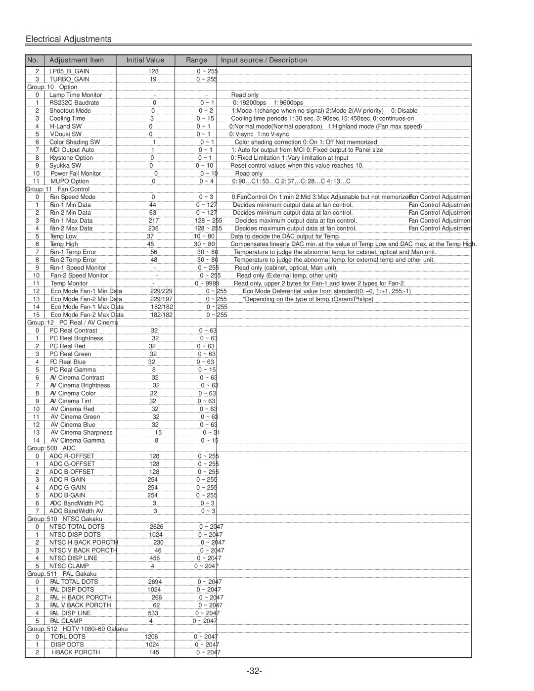
| Adjustment Item | Initial Value | Range | Input source / Description |
|
2 |
| LP05_B_GAIN | 128 | 0 ~ 255 |
|
|
3 |
| TURBO_GAIN | 19 | 0 ~ 255 |
|
|
Group: 10 Option |
|
|
|
| ||
0 |
| Lamp Time Monitor | - | - | Read only |
|
1 |
| RS232C Baudrate | 0 | 0 ~ 1 | 0: 19200bps 1: 9600bps |
|
2 |
| Shootout Mode | 0 | 0 ~ 2 |
| |
3 |
| Cooling Time | 3 | 0 ~ 15 | Cooling time periods 1: 30 sec. 3: 90sec.15: 450sec. 0: |
|
4 |
| 0 | 0 ~ 1 | 0:Normal mode(Normal operation) 1:Highland mode (Fan max speed) |
| |
5 |
| 0 | 0 ~ 1 | 0: |
| |
6 |
| Color Shading SW | 1 | 0 ~ 1 | Color shading correction 0: On 1: Off Not memorized |
|
7 |
| MCI Output Auto | 1 | 0 ~ 1 | 1: Auto for output from MCI 0: Fixed output to Panel size |
|
8 |
| Keystone Option | 0 | 0 ~ 1 | 0: Fixed Limitation 1: Vary limitation at Input |
|
9 |
| Syukka SW | 0 | 0 ~ 10 | Reset control values when this value reaches 10. |
|
10 |
| Power Fail Monitor | 0 | 0 ~ 10 | Read only |
|
11 |
| MUPO Option | 0 | 0 ~ 4 | 0: 90ºC1: 53ºC 2: 37ºC: 28ºC 4: 13ºC |
|
Group: 11 | Fan Control |
|
|
|
| |
0 |
| Fan Speed Mode | 0 | 0 ~ 3 | ✻ Fan Control Adjustment | |
1 |
| 44 | 0 ~ 127 | Decides minimum output data at fan control. | ✻ Fan Control Adjustment | |
2 |
| 63 | 0 ~ 127 | Decides minimum output data at fan control. | ✻ Fan Control Adjustment | |
3 |
| 217 | 128 ~ 255 | Decides maximum output data at fan control. | ✻ Fan Control Adjustment | |
4 |
| 236 | 128 ~ 255 | Decides maximum output data at fan control. | ✻ Fan Control Adjustment | |
5 |
| Temp Low | 37 | 10 ~ 80 | Data to decide the DAC output for Temp. |
|
6 |
| Temp High | 45 | 30 ~ 80 | Compensates linearly DAC min. at the value of Temp Low and DAC max. at the Temp High. | |
7 |
| 56 | 30 ~ 80 | Temperature to judge the abnormal temp. for cabinet, optical and Man unit. |
| |
8 |
| 48 | 30 ~ 80 | Temperature to judge the abnormal temp. for external temp and other unit. |
| |
9 |
| - | 0 ~ 255 | Read only (cabinet, optical, Man unit) |
| |
10 |
| - | 0 ~ 255 | Read only (External temp, other unit) |
| |
11 |
| Temp Monitor | - | 0 ~ 9999 | Read only, upper 2 bytes for |
|
12 |
| Eco Mode | 229/229 | 0 ~ 255 | Eco Mode Deferential value from standard(0: ±0, 1:+1, |
|
13 |
| Eco Mode | 229/197 | 0 ~ 255 | *Depending on the type of lamp. (Osram/Philips) |
|
14 |
| Eco Mode | 182/182 | 0 ~ 255 |
|
|
15 |
| Eco Mode | 182/182 | 0 ~ 255 |
|
|
Group: 12 PC Real / AV Cinema |
|
|
|
| ||
0 |
| PC Real Contrast | 32 | 0 ~ 63 |
|
|
1 |
| PC Real Brightness | 32 | 0 ~ 63 |
|
|
2 |
| PC Real Red | 32 | 0 ~ 63 |
|
|
3 |
| PC Real Green | 32 | 0 ~ 63 |
|
|
4 |
| PC Real Blue | 32 | 0 ~ 63 |
|
|
5 |
| PC Real Gamma | 8 | 0 ~ 15 |
|
|
6 |
| AV Cinema Contrast | 32 | 0 ~ 63 |
|
|
7 |
| AV Cinema Brightness | 32 | 0 ~ 63 |
|
|
8 |
| AV Cinema Color | 32 | 0 ~ 63 |
|
|
9 |
| AV Cinema Tint | 32 | 0 ~ 63 |
|
|
10 |
| AV Cinema Red | 32 | 0 ~ 63 |
|
|
11 |
| AV Cinema Green | 32 | 0 ~ 63 |
|
|
12 |
| AV Cinema Blue | 32 | 0 ~ 63 |
|
|
13 |
| AV Cinema Sharpness | 15 | 0 ~ 31 |
|
|
14 |
| AV Cinema Gamma | 8 | 0 ~ 15 |
|
|
Group: 500 ADC |
|
|
|
| ||
0 |
| ADC | 128 | 0 ~ 255 |
|
|
1 |
| ADC | 128 | 0 ~ 255 |
|
|
2 |
| ADC | 128 | 0 ~ 255 |
|
|
3 |
| ADC | 254 | 0 ~ 255 |
|
|
4 |
| ADC | 254 | 0 ~ 255 |
|
|
5 |
| ADC | 254 | 0 ~ 255 |
|
|
6 |
| ADC BandWidth PC | 3 | 0 ~ 3 |
|
|
7 |
| ADC BandWidth AV | 3 | 0 ~ 3 |
|
|
Group: 510 NTSC Gakaku |
|
|
|
| ||
0 |
| NTSC TOTAL DOTS | 2626 | 0 ~ 2047 |
|
|
1 |
| NTSC DISP DOTS | 1024 | 0 ~ 2047 |
|
|
2 |
| NTSC H BACK PORCTH | 230 | 0 ~ 2047 |
|
|
3 |
| NTSC V BACK PORCTH | 46 | 0 ~ 2047 |
|
|
4 |
| NTSC DISP LINE | 456 | 0 ~ 2047 |
|
|
5 |
| NTSC CLAMP | 4 | 0 ~ 2047 |
|
|
Group: 511 PAL Gakaku |
|
|
|
| ||
0 |
| PAL TOTAL DOTS | 2694 | 0 ~ 2047 |
|
|
1 |
| PAL DISP DOTS | 1024 | 0 ~ 2047 |
|
|
2 |
| PAL H BACK PORCTH | 266 | 0 ~ 2047 |
|
|
3 |
| PAL V BACK PORCTH | 62 | 0 ~ 2047 |
|
|
4 |
| PAL DISP LINE | 533 | 0 ~ 2047 |
|
|
5 |
| PAL CLAMP | 4 | 0 ~ 2047 |
|
|
Group: 512 HDTV |
|
|
|
| ||
0 |
| TOTAL DOTS | 1206 | 0 ~ 2047 |
|
|
1 |
| DISP DOTS | 1024 | 0 ~ 2047 |
|
|
2 |
| H BACK PORCTH | 145 | 0 ~ 2047 |
|
|
|
|
|
|
|
|
|