PLC-XU46 PLC-XU45
PLC-XU46
Contents
Do not Attempt to Servicing Remote Control Unit
Safety Instructions
Specifications
Optical Adjustments Electrical Adjustments
Adjustments after Parts Replacement
Type T4.0AH 250V Fuse Little Fuse INC. Type
Circuit Protections
Recommendation
Possible causes
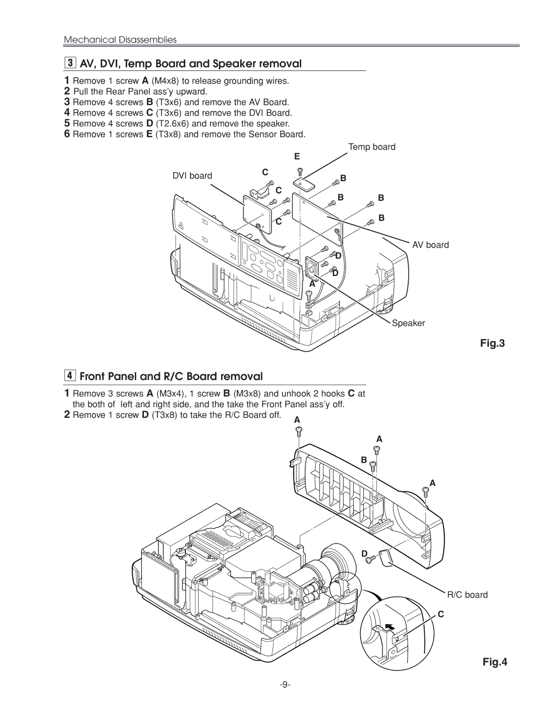
Mechanical Disassemblies
Cabinet Top and Control Panel removal
Main Board removal
Front Panel and R/C Board removal
AV, DVI, Temp Board and Speaker removal
Temp board
DVI board
Filter Board removal
Lamp Ballast Unit removal
Isolation sheet Lamp ballast board SW902
Filter board
Optical Unit removal
Power Box Cover and FansFN901, FN906 removal
Power and P.F. Board removal
⁄1Fans FN902, FN903, FN904 removal
⁄0Fan FN905 removal
Integrator Lens-In disassembly
Optical Parts Disassemblies
Projection Lens removal
Condenser Lens-Out disassembly
Condenser lens disassembly
Relay Lens-Out disassembly
Polarized Glass-In removal
Holder
Optical Unit Top removal
Polarized Glass-Out/Pre-Polarized Glass removal
LCD Panel
Prism Ass’y
Key No. Description
Locations and Directions
LCD Panel/Prism Ass’y Replacement
LCD Panel/Prism Ass’y removal
Color Shading Correction
Lamp Replacement
How to reset Lamp Replace Counter
How to check Lamp Replace Counter
Optical Adjustments
Contrast adjustment
B-CONTRAST Adjustment
Green b Slot B Moving of slot B Slot D Moving of Slot D
Condenser Lens adjustment
Cyan a Slot B Moving of slot B Moving of slot D
Condenser Lens-Out adjustment
Relay lens-Out adjustment
White a Slot B a Moving of slot B
Slot D Moving of slot D
IC1801 is not defective
Electrical Adjustments
Output Voltage adjustment For PLC-XU46
Output Voltage adjustment For PLC-XU45
Fan Voltage adjustment For PLC-XU45
Fan Voltage adjustment For PLC-XU46
C12 NRS adjustment
X12 Pedestal adjustment
V12 Signal Center adjustment
Black Level adjustment
M12 PC Gain adjustment
PC Offset adjustment
AV Gain adjustment
Common Center adjustment
⁄01 Gamma Shift adjustment
⁄11 White Balance adjustment
Adjustment
CXA2101
TB1274
LP05 Turbo
TA1318
Fan Control
Group 10 Option
Group 500 ADC
Group 510 Ntsc Gakaku
Group 514 Hdtv 1035i Gakaku
Group 513 Hdtv 1080i-50 Gakaku
Group 515 Hdtv 720p Gakaku
Group 516 Hdtv 575p Gakaku
Main Board
Test Points and Locations
Abnormality occurs on the power circuit
Troubleshooting
F601
Fuse Thermal sw. Interlock sw
IC801
No picture from DVI source
No picture from Video source
No picture from both of Video and Computer sources
No picture from all of sources
Video Signal processing diagrams
Incorrect operation of VIDEO/COMPUTER mode switching
No audio signals at AV input circuit
No audio output signal at speaker
No power supply at audio circuit
System Control & I/O Port Table IC801
Control Port Functions
Control Port Functions
IIC Bus I/O Expander IC1851 Port Functions
IIC Bus I/O Expander IC2181 Port Functions
IIC Bus DA Converter IC1831 Port Functions
IIC Bus DA Converter IC2161 Port Functions
IIC Bus DA Converter IC1581 Port Functions
IIC Bus DA Converter IC2571 Port Functions
Waveform
VIDEO-IN
Drive TP52R/TP201R Drive TP52G/TP201G Drive TP52B/TP201G
Sync in TP205
Sync OUT IC4101-29 Sync OUT IC4101-28
Sync Drive TP62H Sync Drive TP62V DHS Tpdhs DVS Tpdvs
Ballast SW TP28L
Cleaning with air spray
Cleaning
IC Block Diagrams
BA7078AF Selector, IC6241 CXA2101AQ RGB Matrix, IC4101
IC Block Diagrams
L3E07050 Color, Gamma Correction & Timing Controller , IC401
ML60851 USB I/F, IC9801 M62393 D/A, IC2571
TB1274AF Video Decoder, IC1101 TA1318N AFC Detector, IC6171
IC Block Diagrams
Page
Read Description in the parts list
Electrical Parts List
OUT of Circuit Board
KEY SW Board
Assemblied Boards ME3-XU4500, PLC-XU45
610 292 5609 ASSY,PWB,KEY SW MS6A
Assemblied Boards MF3-XU4600, PLC-XU46
610 299 7330 ASSY,PWB,AV MK8A
AV Board
Transistor
Integrated Circuit
NP-ELECT
DVI Board
610 299 7347 ASSY,PWB,DVI MK8A
Coil
610 301 0939 ASSY,PWB,POWER MK8A
Power Board
610 305 8641 ASSY,PWB,POWER MF3A
For ME3-XU4500, PLC-XU45
MT-POLYEST 0.047U K
Transformer
MF3-XU4600, PLC-XU46
Board
610 301 0946 ASSY,PWB,P.F. MK8A
610 305 8658 ASSY,PWB,P.F. MF3A
Main Board
Line Filter Board
610 301 0953 ASSY,PWB,LINE Filter MK8A
405 014 4608 2SC2412K T146 173 9803 2SC3928A1R 015 8704
IC MM1031XM
SN74AHCT1G14DBVR
C1539 403 164 0204
403 373
C5217 403 164 0204
Network
RB413 645 037 0663 Network 22X4 0.063W R1132
R152 401 8104
R2546 401 105 7909
R336 401 7909
R433 401 105 3901
Fusible
Temp Board
610 304 8932 ASSY,PWB,TEMP ME3A
Diode Integrated Circuit
Accessories
Remote Control
AC Cord
Mechanical Parts List
Optical Parts
67 Red Green Blue
Optical filterWV
Polarized glass
Model PLC-XU46 Model PLC-XU45
52-a
Mechanical Parts List
Cabinet Parts Screws
Optical Parts
Chassis Parts
Page
Printed Wiring Board Drawings
Diagrams & Drawings Schematic Diagrams
PLC-XU45
PLC-XU46
Resistor Reading
Parts description and reading in schematic diagram
Circuit Block Diagram
3VS
5VS
5VS 5VDVI
5VD 9V MCI
Printed Wiring Board Diagrams
AV Sidea DVI Sidea
DVI Sideb
Main Sidea
Sidea
Temp Sidea
Sideb
Main Sideb
Temp Sideb
IC5211
K6S
Power Sidea Power Sideb
K6R
IC671
Line Filter Sidea
KEY SW Sidea
KEY SW Sideb
K6B
A10
Line Filter Baord
Schematic Diagrams PLC-XU45,46 A11 Left
IC681
FA7701V
Ower Supply
Schematic Diagrams PLC-XU45,46 A11 Right
Schematic Diagrams PLC-XU45,46 A12 Left
IC6171
Audio
TA1318AF
Schematic Diagrams PLC-XU45,46 A12 Right
Digital
Schematic Diagrams PLC-XU45,46 A13 Left
Matri
Schematic Diagrams PLC-XU45,46 A13 Right
CG1/CG2-SW
Schematic Diagrams PLC-XU45,46 A14 Left
AD8185ARU
AD8183ARU
3VS C201 TE201E
Schematic Diagrams PLC-XU45,46 A14 Right
Schematic Diagrams PLC-XU45,46 A15 Left
IC301
IC8001
Schematic Diagrams PLC-XU45,46 A15 Right
Digital Color Unformity Correction Timing Control
IC1341
Schematic Diagrams PLC-XU45,46 A16 Left
50-52
Lamp
SUB
Schematic Diagrams PLC-XU45,46 A16 Right
CPU
Memory
Color
Schematic Diagrams PLC-XU45,46 A17 Left
Uniformity & Gamma
Correction
Schematic Diagrams PLC-XU45,46 A17 Right
Level
Shift
Schematic Diagrams PLC-XU45,46 A18 Left
Schematic Diagrams PLC-XU45,46 A18 Right
IC IC
Pin description of diode, transistor and IC