b.
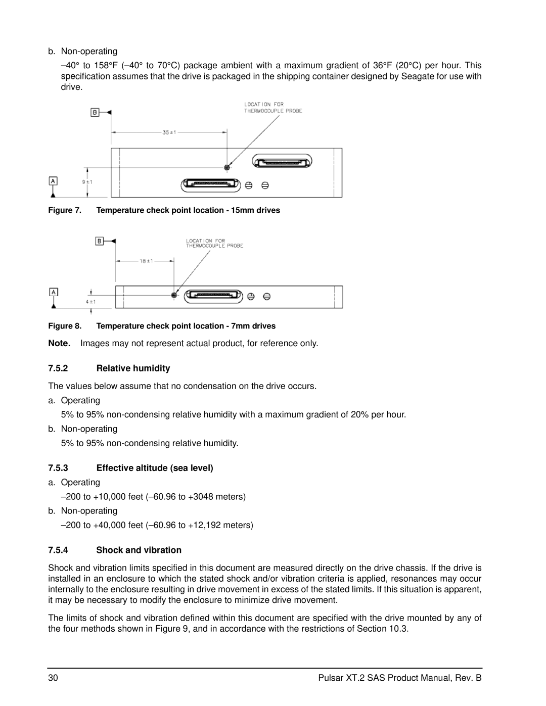
Figure 7. Temperature check point location - 15mm drives
Figure 8. Temperature check point location - 7mm drives
Note. Images may not represent actual product, for reference only.
7.5.2Relative humidity
The values below assume that no condensation on the drive occurs.
a.Operating
5% to 95%
b.
5% to 95%
7.5.3Effective altitude (sea level) a. Operating
7.5.4Shock and vibration
Shock and vibration limits specified in this document are measured directly on the drive chassis. If the drive is installed in an enclosure to which the stated shock and/or vibration criteria is applied, resonances may occur internally to the enclosure resulting in drive movement in excess of the stated limits. If this situation is apparent, it may be necessary to modify the enclosure to minimize drive movement.
The limits of shock and vibration defined within this document are specified with the drive mounted by any of the four methods shown in Figure 9, and in accordance with the restrictions of Section 10.3.
30 | Pulsar XT.2 SAS Product Manual, Rev. B |
