ASSEMBLY
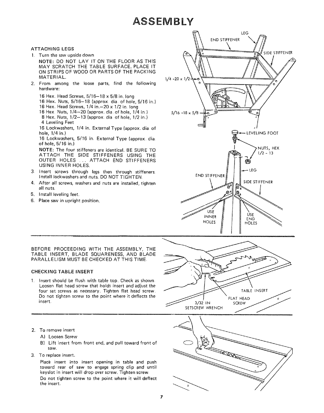
LEG
END STIFFENER
ATTACHING | LEGS |
|
|
|
|
|
|
|
|
| ||||
1, Turn the saw upside down |
|
|
|
|
|
| SIDE STIFFENER | |||||||
|
|
|
|
|
|
| ||||||||
NOTE: DO NOT LAY IT ON THE FLOOR AS THIS | ||||||||||||||
MAY | SCRATCH | THE TABLE SURFACE. PLACE IT | ||||||||||||
ON STRIPS OF WOOD OR PARTS OF THE PACKING | ||||||||||||||
MATERIAL,, |
|
|
|
|
|
|
|
|
|
|
| |||
2_ From among the loose parts, find the following | ||||||||||||||
hardware: |
|
|
|
|
|
|
|
|
|
|
|
| ||
16 | Hex, | Head | Screws, | x 5/8 in, | long |
|
| |||||||
16 | Hex. | Nuts, |
| (approx | dia | of | hole, 5/16 | in.,) | ||||||
16 | Hex, | Head | Screws, | 1/4 | x | t/2 | in. long |
|
| |||||
16Hex |
| Nuts, | dia.ofhoie, | 1/4 | in) | 5/!6 | ||||||||
8 | Hex.. | Nuts, | (approx | dia | of | hole, 1/2 | in.) |
| ||||||
4 | Leveling | Feet |
|
|
|
|
|
|
|
|
| |||
16 | Lockwashers, |
| 1/4 | in. | External | Type | (approx, | dia | of | |||||
hole, | I/4 | in.) |
|
|
|
|
|
|
|
|
|
| ||
I6 | Lockwashers, |
| 5/16 | in. External | Type | (approx | dia | |||||||
of | hole, | 5/16 | in.) |
|
|
|
|
|
|
|
| |||
NOTE: The four stiffeners are identical BE SURE TO | ||||||||||||||
ATTACH |
| THE | SIDE | STIFFENERS |
| USING | THE | |||||||
OUTER | HOLES | .... | ATTACH |
| END | STIFFENERS | ||||||||
USING |
| INNER |
| HOLES.. |
|
|
|
|
|
|
| |||
3. | Insert | screws | through | legs | then through | stiffeners | END STIFFENER |
| |
| Install | Iockwashers | and | nuts. | DO NOT TIGHTEN |
| |||
4. After at1 screws, washers and nuts are installed, tighten |
| SIDE STIFFENER | |||||||
|
| ||||||||
| all nuts_ |
|
|
|
|
|
|
| |
5o | install | leveling | feet.. |
|
|
|
|
|
|
6,. | Place saw in upright | position,. |
|
|
|
| |||
|
|
|
|
|
|
|
| INNER | END |
|
|
|
|
|
|
|
|
| |
|
|
|
|
|
|
|
| HOLES | HOLES |
BEFORE PROCEEDING WITH THE ASSEMBLY, THE
TABLE 1NSERT, BLADE SQUARENESS, AND BLADE
PARALLELISM MUST BE CHECKED AT THIS TIME,
CHECKING | TABLE | INSERT |
|
|
|
|
| |
Insert should be flush with table top, Check as shown |
|
|
| |||||
Loosen flat head screw that holds insert and adjust the |
|
|
| |||||
four set | screws | as necessary,, | Tighten flat | head screw, | TABLE INSERT | j | ||
Do not | tighten | screw to the | point where it | deflects the | ||||
FLAT HEAD | _ | _ ._ | ||||||
insert |
|
|
|
| ||||
|
|
| 3/32 | iN |
|
| ||
|
|
|
|
|
| |||
|
|
|
| SETSCREW | WRENCH |
|
| |
2.To remove insert
A)Loosen Screw
B)Lift insert from front end, and purl toward front of saw.
3_ To replace insert°
Place insert into insert opening in table and push
toward rear of saw to engage spring clip and until keyslot in insert wif] drop over screw, Tighten screw.
Do not tighten screw to the point where it wifl deflect the insert.