0

#.,


CONNECTION

DIAGRAM


WARNING:

ELECTRICAL

SHOCK

HAZARD


DISCONNECT

BEFORE

SERVICING


R

MAi-NUM_-TQ


R


Q


FIELD


ROLLOUT SWITCH 1 TO 3 IN


CONNECTION


I

C1

-----

_

R


SERIES

DEPENDING

ON MODEL.


BOX


INTERLOCK


_

GAS

VALVE I


.....................


SWITCH

[-

_


1612t

- -----

_


BL


_

PRESSURE

SWITCH

115V

_


SK _


I

I

-


P Ji

t

_

r---

:


1 TO 2 IN

SERIES

60HZ

NEUT_RAL_ t''''_

--BE

_


: DEPENDINGON


*GR

I

I

IbOI


!


IGNITER

"

I

_LY-gTJ

_


MODEL


/_

_1


I

L_

I


r_F


q

:: /


/_/.L//NOTE

2

"

ELD)

I


SENS%I --C_i/


L_

q

HI VOLT

FIELD


C2


co_#_TC%RSI BL


_ _3'


1

,

,


ONLY


W

I


II191

,I

°


I

I

I

I

tLP_


I

I L,I,_-C%

I_

s'KiI


....

p


BK


,

BL


SWITCH


LADDER DIAGRAM


HOT


115V.-60HZ

NEUTRAL


/_

INTERLOCK


07


/_


>SWITCH


GR


q _ _(_

i_)

CONT

(OPT)

N

::_

II


oM1


MLO (BL)


H

_)

M2

LO (R)


It


mOO >OO _mr-

Ooo Z_z

-n

mE_ m r-mr-

>m>

moo m

3

I L_ ? !, % E_KOI I _,l ILP MWoIDTECHsONLY)]


BK--


'


,


L


q

H


i,.....co_,J,__-.--,_1


Idl

II

,,F'ELD'NSTALLEB)


H

TRANSFORMER


j

H


(SOME MODELS)

_


_


11,)_2cCOM b_Z/I jl

_,l_llll

I

w _

i

_1


:::::::_ _

EAC


EACC N_:


N


_

_

HUM


HUMO====

:_


N

=:=6


I

_

DATA


I UI I BKw


(_: uO_ 115V,


o==


L1

_

TRANSFORMER


....


N


ROLLOUT

SWITCH


1 TO 3 IN SERIES


DEPENDING

ON

MODEL

I


b c FURNACE


_

L1

1

I

v

_

I BR

(_

24MAC

O_


i


@

MAiN LIMI_

_)_


COM


I

I

-----le_


_o

>

COoL_l

I


F1

5A

FUSE


5

1


PRESSURE SWITCH

I

II

_


G


FURNACE


!

DEPENDING

ON MODEL


CONTROL


@I -"_ii

'


[JB


I


I

I


CAPACITOR


L


,,I


R


s_

]


SOME MODELS)


I

I

Y I


CAPACITOR


SL

0


I


_

--


i_o_--- 1


III


c N r i_


SWl FCH


___


_ 0S_:__

_-


i _:LOt

CO_ORCOD@©®Q_ _


THERMOSTAT


_


I(_LACRED:LOEP/OKMHI I

I I

I


I I(FI............BVSS

) ! I


NOTE:

1, MOST

VOLT METERS

WILL READ 13-16

VOLTS

TO

--

LINE VOLTAGE

FACTORY


/ BROWN

BR I

_1-1


CHwASSIHSIOTNHBOTHSTIID,ESDOFcAvN(OPEANLtMITcOLRTPRESSURE

--

LINE VOLTAGE

FIELD


oGRRAE_NE

0G


"T


il:ttl_.

7>


C


c


2


C


f-

.

:Z

1:_


m

C

_n

N

P

2, FACTORY CONNECTED

WHEN

BVSS, (CHIMNEY

ADAPTOR

LOW VOLTAGE FACTORY


_'

I ....

_

WIRE AS SUPPLIED WITH

ACCESSORY_,T)ORLPPRESSSW,TCS,SNOT,NSTALLED---- LOWVOLTAGEF,ELO/'%E

"_

IF ANY OF THE ORIGINAL

z_NO_E 2


k

:

THE APPLIANCE MUST

BE


_

INTERNAL

CIRCUIT BOARD

WIRING


YELLOW

Y

I


REPLACED

IT MUST BE

[329530-101 REV.A I

"_ SEE MANUALS FOR

ADJUSTING

SPEED TAPS

FOR

RECTIFIED

AC VOLTAGE

FACTORY

p


REPLACED

WITH TYPE

PROPER HEATING,

COOLING

& CIRCULATING

SPEEDS.


URPLE

P


AWM-105_C WIRE OR EQUIV,


o

2

2

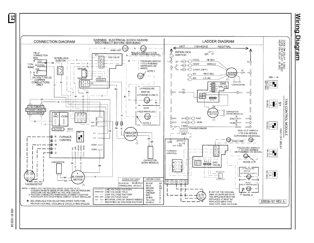
Page 54
Image 54
Sears N9MP2050B12B1, N9MP2080F16B1, N9MP2075B12B1, N9MP2100F14B1, N9MP2125J20B1, 9MPD100J14B1 Ilttl, Neutral t, Data, UI I BKw

9MPD100J20B1, N9MP2100J20B1, 9MPD050F12B1, N9MP1100J20B1, N9MP1125J20B1 specifications

The Sears N9MP1075B12B1, N9MPD125L20B1, N9MP1050B12B1, N9MPD080J16B1, and N9MP2125J20B1 are part of the trusted line of gas furnaces manufactured by Sears, specifically designed to deliver reliable heating solutions for residential applications. These models incorporate cutting-edge technology and robust engineering, making them popular choices among homeowners looking for efficiency and comfort.

One of the main features of these models is their high-efficiency operation. With Annual Fuel Utilization Efficiency (AFUE) ratings exceeding 90%, these furnaces convert a significant portion of fuel into usable heat, thereby reducing energy costs. The N9MP series employs a multi-speed blower system that optimizes airflow for enhanced comfort while minimizing noise levels, ensuring a pleasant indoor environment.

The N9MPD125L20B1 and N9MPD080J16B1 variants highlight their adaptability through dual-stage heating capabilities. This technology allows the furnace to adjust its output based on the thermal demands of the home, preventing energy wastage during milder conditions while providing robust heating during extreme cold spells. The two-stage combustion process not only improves comfort but also contributes to lower greenhouse gas emissions.

Durability is another hallmark of these Sears models. With heavy-duty heat exchangers crafted from high-quality materials, they are built to withstand the rigors of regular use. Additionally, the inclusion of advanced safety mechanisms ensures that the system operates securely, reducing potential risks associated with gas furnaces.

The N9MP2125J20B1 model stands out due to its whisper-quiet operation. Homeowners can enjoy a warm home without the disruptive sound commonly associated with traditional heating systems, thanks to the insulated cabinet design and efficient blower operation.

Furthermore, these models come equipped with user-friendly digital thermostats, which allow precise temperature control and programmable settings, enabling homeowners to tailor their heating needs to fit their lifestyle. The compatibility with smart home systems also adds convenience, enabling users to manage their heating remotely, saving even more energy.

In conclusion, the Sears N9MP1075B12B1, N9MPD125L20B1, N9MP1050B12B1, N9MPD080J16B1, and N9MP2125J20B1 gas furnaces exemplify innovation in heating technology. Their energy-efficient designs, advanced features, and durable construction make them reliable choices for homeowners seeking comfort and sustainability in their heating solutions.