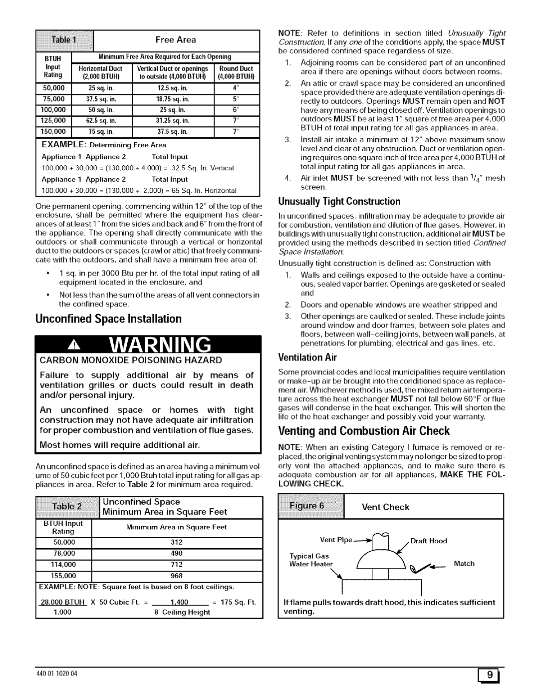
Free Area


BTUH


MinimumFreeArea Requiredfor Each Opening

Input

HorizontalDuct

VerticalDuctor openings

Round Duct

Rating


(2,000 BTUH)


to outside(4,000 BTUH)

(4,000 BTUH)

50,000


25 sq. in.


12.5 sq. in.

4"

75,000


37.5 sq. in.


1825 sq. in.

5"

100,000


50 sq. in.


25 sq. in.

6"

125,000


62.5 sq. in.


3125 sq. in.

7"

150,000


75 sq. in.


37.5 sq. in.

7"

EXAMPLE:

Determining

Free Area


Appliance

1

Appliance

2

Total

Input


100,000

+ 30,000 = (130,000

+ 4,000) =

32.5 Sq. In. Vertical

Appliance

1

Appliance

2

Total

Input


100,000 + 30,000 = (130,000 + 2,000) = 65 Sq. In. Horizontal

One permanent opening, commencing within 12" of the top of the

enclosure, shall be permitted where the equipment has clear- ances of at least 1" from the sides and back and 6" from the front of

the appliance. The opening shall directly communicate with the

outdoors or shall communicate through a vertical or horizontal duct to the outdoors or spaces (crawl or attic) that freely communi- cate with the outdoors, and shall have a minimum free area of:

1 sq. in per 3000 Btu per hr. of the total input rating of all equipment located in the enclosure, and

Not less than the sum ofthe areas of all vent connectors in the confined space.

Unconfined Space Installation

CARBON MONOXIDE POISONING HAZARD

Failure to supply additional air by means of ventilation grilles or ducts could result in death and/or personal injury.

An unconfined space or homes with tight construction may not have adequate air infiltration for proper combustion and ventilation of flue gases.

Most homes will require additional air.

An unconfined space is defined as an area having a minimum vol- ume of 50 cubic feet per 1,000 Btuh total input rating for all gas ap- pliances in area. Refer to Table 2 for minimum area required.


I Unconfined

Space


Minimum Area in Square Feet

BTUH Input

Minimum Area in Square Feet

Rating


50,000


312


78,000


49O


114,000


712


155,000


968


EXAMPLE: NOTE: Square feet is based on 8 foot ceilings.

28,000 BTUH X 50 Cubic Ft. =

1,400

= 175 Sq. Ft.

1,000


8'Ceiling

Height

NOTE: Refer to definitions in section titled Unusually Tight

Construction, If any one of the conditions apply, the space MUST be considered confined space regardless of size.

1.Adjoining rooms can be considered part of an unconfined area if there are openings without doors between rooms.

2.An attic or crawl space may be considered an unconfined space provided there are adequate ventilation openings di- rectly to outdoors. Openings MUST remain open and NOT have any means of being closed off. Ventilation openings to outdoors MUST be at least 1" square of free area per 4,000 BTUH of total input rating for all gas appliances in area.

3.Install air intake a minimum of 12" above maximum snow level and clear of any obstruction. Duct or ventilation open- ing requires one square inch of free area per 4,000 BTU H of total input rating for all gas appliances in area.

4.Air inlet MUST be screened with not less than 1/4" mesh screen.

Unusually Tight Construction

In unconfined spaces, infiltration may be adequate to provide air

for combustion, ventilation and dilution of flue gases. However, in

buildings with unusually tight construction, additional air MUST be provided using the methods described in section titled Confined Space Installation:

Unusually tight construction is defined as: Construction with

1.Walls and ceilings exposed to the outside have a continu- ous, sealed vapor barrier. Openings are gasketed or sealed and

2, Doors and openable windows are weather stripped and

3.Other openings are caulked or sealed. These includejoints around window and door frames, between sole plates and floors, between wall-ceiling joints, between wall panels, at

penetrations for plumbing, electrical and gas lines, etc.

Ventilation Air

Some provincial codes and local municipalities require ventilation or make-up air be brought into the conditioned space as replace- ment air. Whichever method is used, the mixed return air tempera- ture across the heat exchanger MUST not fall below 60°F or flue gases will condense in the heat exchanger. This will shorten the life of the heat exchanger and possibly void your warranty.

Venting and Combustion Air Check

NOTE: When an existing Category I furnace is removed or re- placed, the original venting system may no longer be sized to prop- erly vent the attached appliances, and to make sure there is adequate combustion air for all appliances, MAKE THE FOL-

LOWING CHECK.


Vent

Check


Vent Pipe----_,l

I 7

Draft Hood

Typical Gas

f

_'_


WaterHeate

/ i

i

Match

I


I

If flame pulls towards draft hood, this indicates sufficient

venting.

44001 102004

[_

Page 9
Image 9
Sears 9MPD125L20B1, N9MP2050B12B1 Venting and Combustion Air Check, Example, Unusually Tight Construction, Ventilation Air

9MPD100J20B1, N9MP2100J20B1, 9MPD050F12B1, N9MP1100J20B1, N9MP1125J20B1 specifications

The Sears N9MP1075B12B1, N9MPD125L20B1, N9MP1050B12B1, N9MPD080J16B1, and N9MP2125J20B1 are part of the trusted line of gas furnaces manufactured by Sears, specifically designed to deliver reliable heating solutions for residential applications. These models incorporate cutting-edge technology and robust engineering, making them popular choices among homeowners looking for efficiency and comfort.

One of the main features of these models is their high-efficiency operation. With Annual Fuel Utilization Efficiency (AFUE) ratings exceeding 90%, these furnaces convert a significant portion of fuel into usable heat, thereby reducing energy costs. The N9MP series employs a multi-speed blower system that optimizes airflow for enhanced comfort while minimizing noise levels, ensuring a pleasant indoor environment.

The N9MPD125L20B1 and N9MPD080J16B1 variants highlight their adaptability through dual-stage heating capabilities. This technology allows the furnace to adjust its output based on the thermal demands of the home, preventing energy wastage during milder conditions while providing robust heating during extreme cold spells. The two-stage combustion process not only improves comfort but also contributes to lower greenhouse gas emissions.

Durability is another hallmark of these Sears models. With heavy-duty heat exchangers crafted from high-quality materials, they are built to withstand the rigors of regular use. Additionally, the inclusion of advanced safety mechanisms ensures that the system operates securely, reducing potential risks associated with gas furnaces.

The N9MP2125J20B1 model stands out due to its whisper-quiet operation. Homeowners can enjoy a warm home without the disruptive sound commonly associated with traditional heating systems, thanks to the insulated cabinet design and efficient blower operation.

Furthermore, these models come equipped with user-friendly digital thermostats, which allow precise temperature control and programmable settings, enabling homeowners to tailor their heating needs to fit their lifestyle. The compatibility with smart home systems also adds convenience, enabling users to manage their heating remotely, saving even more energy.

In conclusion, the Sears N9MP1075B12B1, N9MPD125L20B1, N9MP1050B12B1, N9MPD080J16B1, and N9MP2125J20B1 gas furnaces exemplify innovation in heating technology. Their energy-efficient designs, advanced features, and durable construction make them reliable choices for homeowners seeking comfort and sustainability in their heating solutions.