The air intake coupling is sized for 2" PVC pipe.

Install the combustion air pipe to the air intake coupling using RTV sealant to provide for future serviceability.

Vent Pipe Connection

Install the vent pipe grommet to the furnace panel. Locate the grommet in the furnace panel at a location directly away from the

vent fitting on the combustion blower. The grommet snaps into the

3" hole plug from the furnace panel. NOTE: Depending on the installation position, the vent pipe grommet will be installed to the

top panel or to the alternate location on the side panels. If needed, remove the 3" hole plug from the furnace panel and relocate to the open hole in the furnace panel. (See Figure 9 or Figure 18)

Install the vent pipe to the rubber coupling, the vent fitting or the PVC vent extension pipe. Securely attach using the clamp or PVC cement as required.

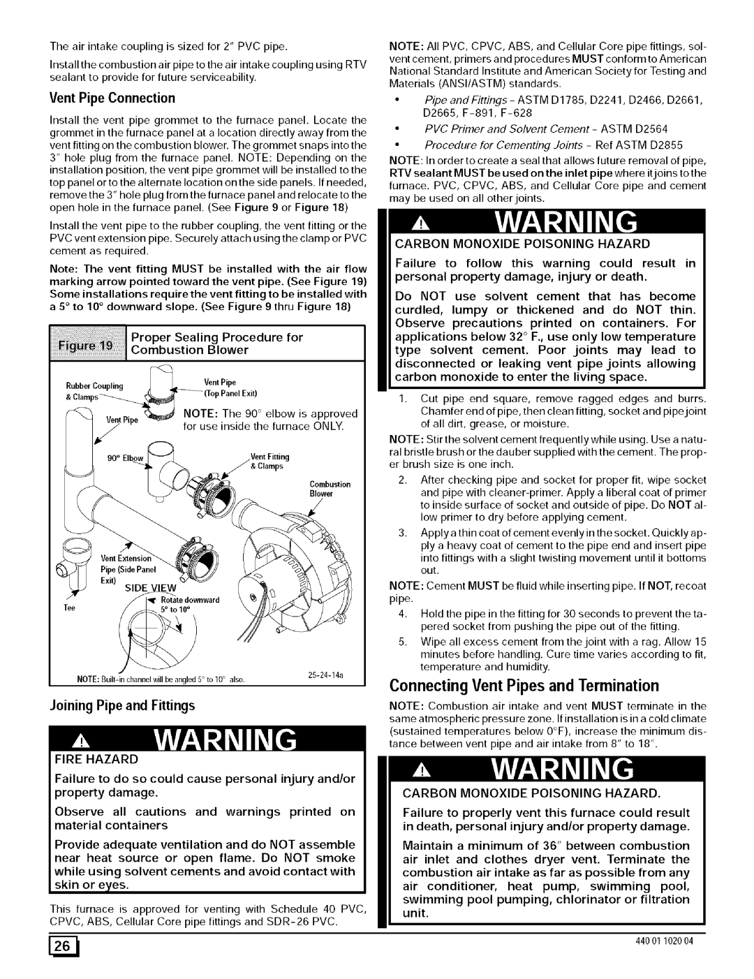
Note: The vent fitting MUST be installed with the air flow marking arrow pointed toward the vent pipe. (See Figure 19)

Some

installations

require

the vent

fitting

to be

installed

with

a 5 ° to

10 ° downward

slope.

(See

Figure

9 thru

Figure

18)


Proper

Sealing

Procedure for


Combustion

Blower


RubberCoupling

_Vent


Pipe


& Clamps'__


_(Top

PanelExit)

VentPine t_

NOTE

: The

90 ° elbow is approved


r

for

use

inside

the furnace ONLY.

90 ° Elbow

& Clamps

Combustion

Blower

Pipe (Side Panel

NOTE: All PVC, CPVC, ABS, and Cellular Core pipe fittings, sol- vent cement, primers and procedures MUST conform to American National Standard Institute and American Society for Testing and Materials (ANSI/ASTM) standards.

PipeandFittings-ASTMD1785, D2241,D2466, D2661,

D2665, F-891, F-628

PVC Primer and Solvent Cement - ASTM D2564

Procedure for Cementing Joints - Ref ASTM D2855

NOTE: In order to create a seal that allows future removal of pipe, RTV sealant MUST be used on the inlet pipe where it joins to the furnace. PVC, CPVC, ABS, and Cellular Core pipe and cement may be used on all other joints.

CARBON MONOXIDE POISONING HAZARD

Failure to follow this warning could result in personal property damage, injury or death.

Do NOT use solvent cement that has become curdled, lumpy or thickened and do NOT thin. Observe precautions printed on containers. For applications below 32 ° F., use only low temperature type solvent cement. Poor joints may lead to disconnected or leaking vent pipe joints allowing carbon monoxide to enter the living space.

1.Cut pipe end square, remove ragged edges and burrs. Chamfer end of pipe, then clean fitting, socket and pipe joint of all dirt, grease, or moisture.

NOTE: Stir the solvent cement frequently while using. Use a natu- ral bristle brush or the dauber supplied with the cement. The prop- er brush size is one inch.

2.After checking pipe and socket for proper fit, wipe socket

and pipe with cleaner-primer. Apply a liberal coat of primer to inside surface of socket and outside of pipe. Do NOT al- low primer to dry before applying cement.

3.Apply a thin coat of cement evenly in the socket. Quickly ap- ply a heavy coat of cement to the pipe end and insert pipe

into fittings with a slight twisting movement until it bottoms out.

Exit)

Tee

SIDE VIEW

wnward

25-24-14a

NOTE: Cement MUST be fluid while inserting pipe. If NOT, recoat pipe.

4.Hold the pipe in the fitting for 30 seconds to prevent the ta- pered socket from pushing the pipe out of the fitting.

5.Wipe all excess cement from the joint with a rag. Allow 15 minutes before handling. Cure time varies according to fit,

temperature and humidity.

NOTE: Built-in channel will be angled 5° to 10° also.

Joining Pipe and Fittings

FIRE HAZARD

Failure to do so could cause personal injury and/or property damage.

Observe all cautions and warnings printed on material containers

Provide adequate ventilation and do NOT assemble near heat source or open flame. Do NOT smoke while using solvent cements and avoid contact with skin or e,yes.

This furnace is approved for venting with Schedule 40 PVC, CPVC, ABS, Cellular Core pipe fittings and SDR-26 PVC.

Connecting Vent Pipes and Termination

NOTE: Combustion air intake and vent MUST terminate in the

same atmospheric pressure zone. If installation is in a cold climate

(sustained temperatures below O°F), increase the minimum dis- tance between vent pipe and air intake from 8" to 18".

CARBON MONOXIDE POISONING HAZARD.

Failure to properly vent this furnace could result in death, personal injury and/or property damage.

Maintain a minimum of 36" between combustion air inlet and clothes dryer vent. Terminate the combustion air intake as far as possible from any

air conditioner, heat pump, swimming pool,

swimming pool pumping, chlorinator or filtration unit.

[_

440 01 1020 04

Page 26
Image 26
Sears 9MPD100J20B1 Connecting Vent Pipes and Termination, Vent Pipe Connection, Proper Sealing Procedure for Combustion

9MPD100J20B1, N9MP2100J20B1, 9MPD050F12B1, N9MP1100J20B1, N9MP1125J20B1 specifications

The Sears N9MP1075B12B1, N9MPD125L20B1, N9MP1050B12B1, N9MPD080J16B1, and N9MP2125J20B1 are part of the trusted line of gas furnaces manufactured by Sears, specifically designed to deliver reliable heating solutions for residential applications. These models incorporate cutting-edge technology and robust engineering, making them popular choices among homeowners looking for efficiency and comfort.

One of the main features of these models is their high-efficiency operation. With Annual Fuel Utilization Efficiency (AFUE) ratings exceeding 90%, these furnaces convert a significant portion of fuel into usable heat, thereby reducing energy costs. The N9MP series employs a multi-speed blower system that optimizes airflow for enhanced comfort while minimizing noise levels, ensuring a pleasant indoor environment.

The N9MPD125L20B1 and N9MPD080J16B1 variants highlight their adaptability through dual-stage heating capabilities. This technology allows the furnace to adjust its output based on the thermal demands of the home, preventing energy wastage during milder conditions while providing robust heating during extreme cold spells. The two-stage combustion process not only improves comfort but also contributes to lower greenhouse gas emissions.

Durability is another hallmark of these Sears models. With heavy-duty heat exchangers crafted from high-quality materials, they are built to withstand the rigors of regular use. Additionally, the inclusion of advanced safety mechanisms ensures that the system operates securely, reducing potential risks associated with gas furnaces.

The N9MP2125J20B1 model stands out due to its whisper-quiet operation. Homeowners can enjoy a warm home without the disruptive sound commonly associated with traditional heating systems, thanks to the insulated cabinet design and efficient blower operation.

Furthermore, these models come equipped with user-friendly digital thermostats, which allow precise temperature control and programmable settings, enabling homeowners to tailor their heating needs to fit their lifestyle. The compatibility with smart home systems also adds convenience, enabling users to manage their heating remotely, saving even more energy.

In conclusion, the Sears N9MP1075B12B1, N9MPD125L20B1, N9MP1050B12B1, N9MPD080J16B1, and N9MP2125J20B1 gas furnaces exemplify innovation in heating technology. Their energy-efficient designs, advanced features, and durable construction make them reliable choices for homeowners seeking comfort and sustainability in their heating solutions.