[8] TROUBLESHOOTING
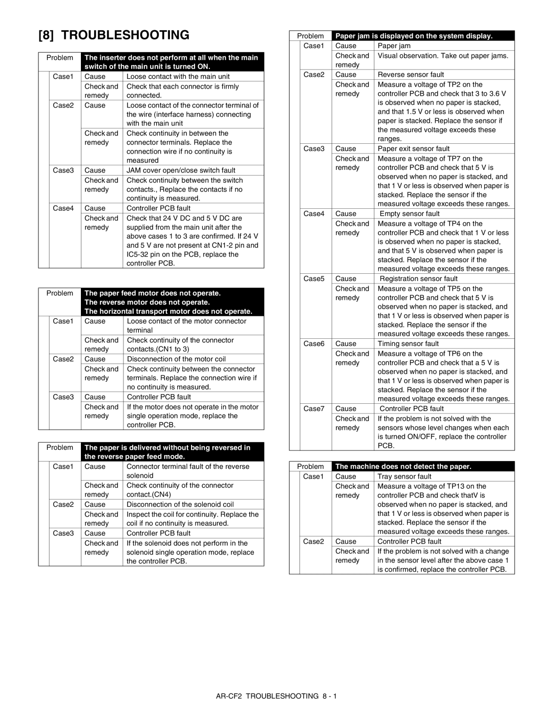
Problem | The inserter does not perform at all when the main | ||
|
| switch of the main unit is turned ON. | |
| Case1 | Cause | Loose contact with the main unit |
|
| Check and | Check that each connector is firmly |
|
| remedy | connected. |
| Case2 | Cause | Loose contact of the connector terminal of |
|
|
| the wire (interface harness) connecting |
|
|
| with the main unit |
|
| Check and | Check continuity in between the |
|
| remedy | connector terminals. Replace the |
|
|
| connection wire if no continuity is |
|
|
| measured |
| Case3 | Cause | JAM cover open/close switch fault |
|
| Check and | Check continuity between the switch |
|
| remedy | contacts., Replace the contacts if no |
|
|
| continuity is measured. |
| Case4 | Cause | Controller PCB fault |
|
| Check and | Check that 24 V DC and 5 V DC are |
|
| remedy | supplied from the main unit after the |
|
|
| above cases 1 to 3 are confirmed. If 24 V |
|
|
| and 5 V are not present at |
|
|
| |
|
|
| controller PCB. |
Problem | The paper feed motor does not operate. | ||
|
| The reverse motor does not operate. | |
|
| The horizontal transport motor does not operate. | |
| Case1 | Cause | Loose contact of the motor connector |
|
|
| terminal |
|
| Check and | Check continuity of the connector |
|
| remedy | contacts.(CN1 to 3) |
| Case2 | Cause | Disconnection of the motor coil |
|
| Check and | Check continuity between the connector |
|
| remedy | terminals. Replace the connection wire if |
|
|
| no continuity is measured. |
| Case3 | Cause | Controller PCB fault |
|
| Check and | If the motor does not operate in the motor |
|
| remedy | single operation mode, replace the |
|
|
| controller PCB. |
Problem | The paper is delivered without being reversed in | ||
|
| the reverse paper feed mode. | |
| Case1 | Cause | Connector terminal fault of the reverse |
|
|
| solenoid |
|
| Check and | Check continuity of the connector |
|
| remedy | contact.(CN4) |
| Case2 | Cause | Disconnection of the solenoid coil |
|
| Check and | Inspect the coil for continuity. Replace the |
|
| remedy | coil if no continuity is measured. |
| Case3 | Cause | Controller PCB fault |
|
| Check and | If the solenoid does not perform in the |
|
| remedy | solenoid single operation mode, replace |
|
|
| the controller PCB. |
Problem | Paper jam is displayed on the system display. | ||
| Case1 | Cause | Paper jam |
|
| Check and | Visual observation. Take out paper jams. |
|
| remedy |
|
| Case2 | Cause | Reverse sensor fault |
|
| Check and | Measure a voltage of TP2 on the |
|
| remedy | controller PCB and check that 3 to 3.6 V |
|
|
| is observed when no paper is stacked, |
|
|
| and that 1.5 V or less is observed when |
|
|
| paper is stacked. Replace the sensor if |
|
|
| the measured voltage exceeds these |
|
|
| ranges. |
| Case3 | Cause | Paper exit sensor fault |
|
| Check and | Measure a voltage of TP7 on the |
|
| remedy | controller PCB and check that 5 V is |
|
|
| observed when no paper is stacked, and |
|
|
| that 1 V or less is observed when paper is |
|
|
| stacked. Replace the sensor if the |
|
|
| measured voltage exceeds these ranges. |
| Case4 | Cause | Empty sensor fault |
|
| Check and | Measure a voltage of TP4 on the |
|
| remedy | controller PCB and check that 1 V or less |
|
|
| is observed when no paper is stacked, |
|
|
| and that 5 V is observed when paper is |
|
|
| stacked. Replace the sensor if the |
|
|
| measured voltage exceeds these ranges. |
| Case5 | Cause | Registration sensor fault |
|
| Check and | Measure a voltage of TP5 on the |
|
| remedy | controller PCB and check that 5 V is |
|
|
| observed when no paper is stacked, and |
|
|
| that 1 V or less is observed when paper is |
|
|
| stacked. Replace the sensor if the |
|
|
| measured voltage exceeds these ranges. |
| Case6 | Cause | Timing sensor fault |
|
| Check and | Measure a voltage of TP6 on the |
|
| remedy | controller PCB and check that a 5 V is |
|
|
| observed when no paper is stacked, and |
|
|
| that 1 V or less is observed when paper is |
|
|
| stacked. Replace the sensor if the |
|
|
| measured voltage exceeds these ranges. |
| Case7 | Cause | Controller PCB fault |
|
| Check and | If the problem is not solved with the |
|
| remedy | sensors whose level changes when each |
|
|
| is turned ON/OFF, replace the controller |
|
|
| PCB. |
Problem | The machine does not detect the paper. | ||
| Case1 | Cause | Tray sensor fault |
|
| Check and | Measure a voltage of TP13 on the |
|
| remedy | controller PCB and check thatV is |
|
|
| observed when no paper is stacked, and |
|
|
| that 1 V or less is observed when paper is |
|
|
| stacked. Replace the sensor if the |
|
|
| measured voltage exceeds these ranges. |
| Case2 | Cause | Controller PCB fault |
|
| Check and | If the problem is not solved with a change |
|
| remedy | in the sensor level after the above case 1 |
|
|
| is confirmed, replace the controller PCB. |