C. Circuit Detail
(1) Communication Circuit
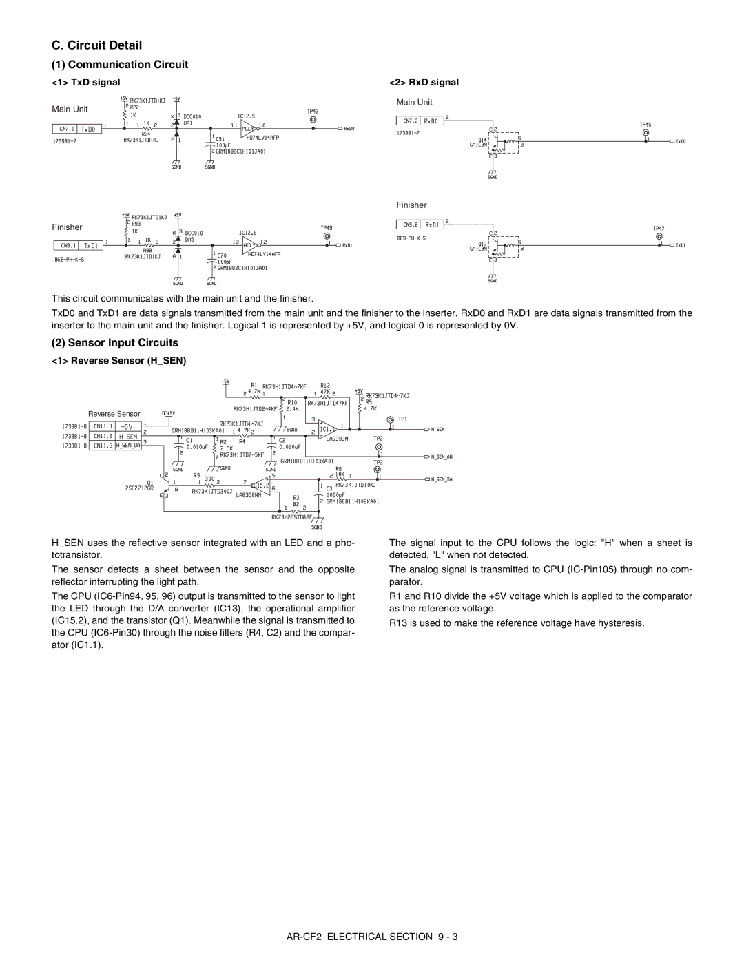
<1> TxD signal | <2> RxD signal |
Main Unit
Main Unit
Finisher
Finisher
This circuit communicates with the main unit and the finisher.
TxD0 and TxD1 are data signals transmitted from the main unit and the finisher to the inserter. RxD0 and RxD1 are data signals transmitted from the inserter to the main unit and the finisher. Logical 1 is represented by +5V, and logical 0 is represented by 0V.
(2) Sensor Input Circuits
<1> Reverse Sensor (H_SEN)
Reverse Sensor
H_SEN uses the reflective sensor integrated with an LED and a pho- totransistor.
The sensor detects a sheet between the sensor and the opposite reflector interrupting the light path.
The CPU
The signal input to the CPU follows the logic: "H" when a sheet is detected, "L" when not detected.
The analog signal is transmitted to CPU
R1 and R10 divide the +5V voltage which is applied to the comparator as the reference voltage.
R13 is used to make the reference voltage have hysteresis.