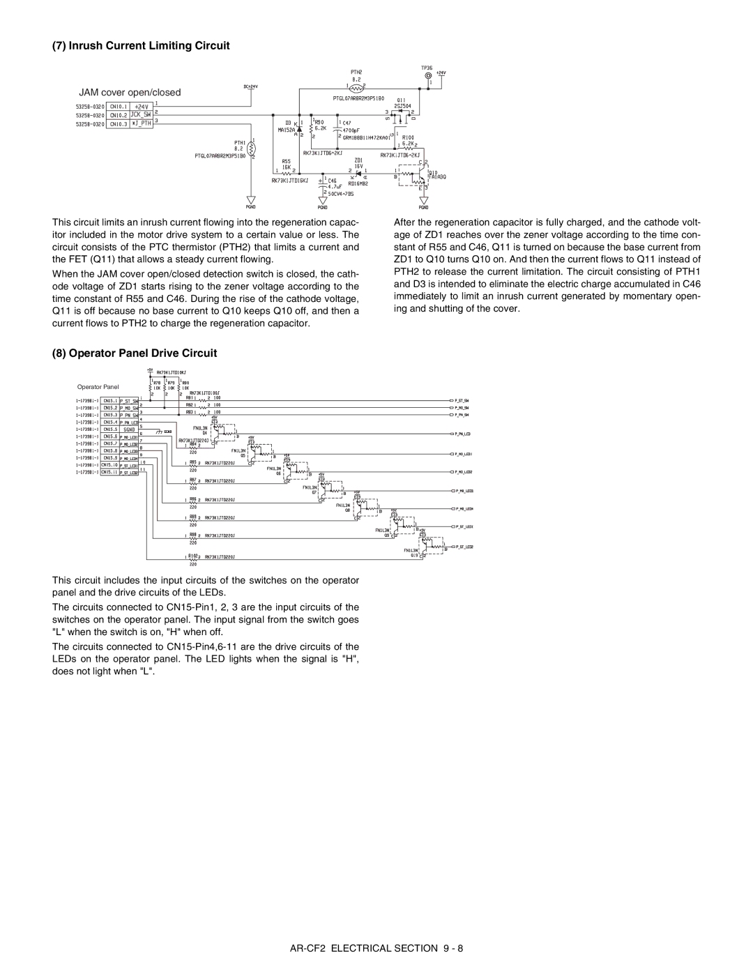
(7)Inrush Current Limiting Circuit
JAM cover open/closed
This circuit limits an inrush current flowing into the regeneration capac- itor included in the motor drive system to a certain value or less. The circuit consists of the PTC thermistor (PTH2) that limits a current and the FET (Q11) that allows a steady current flowing.
When the JAM cover open/closed detection switch is closed, the cath- ode voltage of ZD1 starts rising to the zener voltage according to the time constant of R55 and C46. During the rise of the cathode voltage, Q11 is off because no base current to Q10 keeps Q10 off, and then a current flows to PTH2 to charge the regeneration capacitor.
(8) Operator Panel Drive Circuit
Operator Panel
This circuit includes the input circuits of the switches on the operator panel and the drive circuits of the LEDs.
The circuits connected to
The circuits connected to
After the regeneration capacitor is fully charged, and the cathode volt- age of ZD1 reaches over the zener voltage according to the time con- stant of R55 and C46, Q11 is turned on because the base current from ZD1 to Q10 turns Q10 on. And then the current flows to Q11 instead of PTH2 to release the current limitation. The circuit consisting of PTH1 and D3 is intended to eliminate the electric charge accumulated in C46 immediately to limit an inrush current generated by momentary open- ing and shutting of the cover.